

Low profile connector
A technology for connectors and electrical connectors, applied in the direction of connection, fixed connection, electrical components, etc., can solve problems such as unreliable brazing, mismatch, etc., and achieve the effect of reducing stack height and high input/output density
- Summary
- Abstract
- Description
- Claims
- Application Information
AI Technical Summary
Problems solved by technology
Method used
Image

Examples
Embodiment Construction
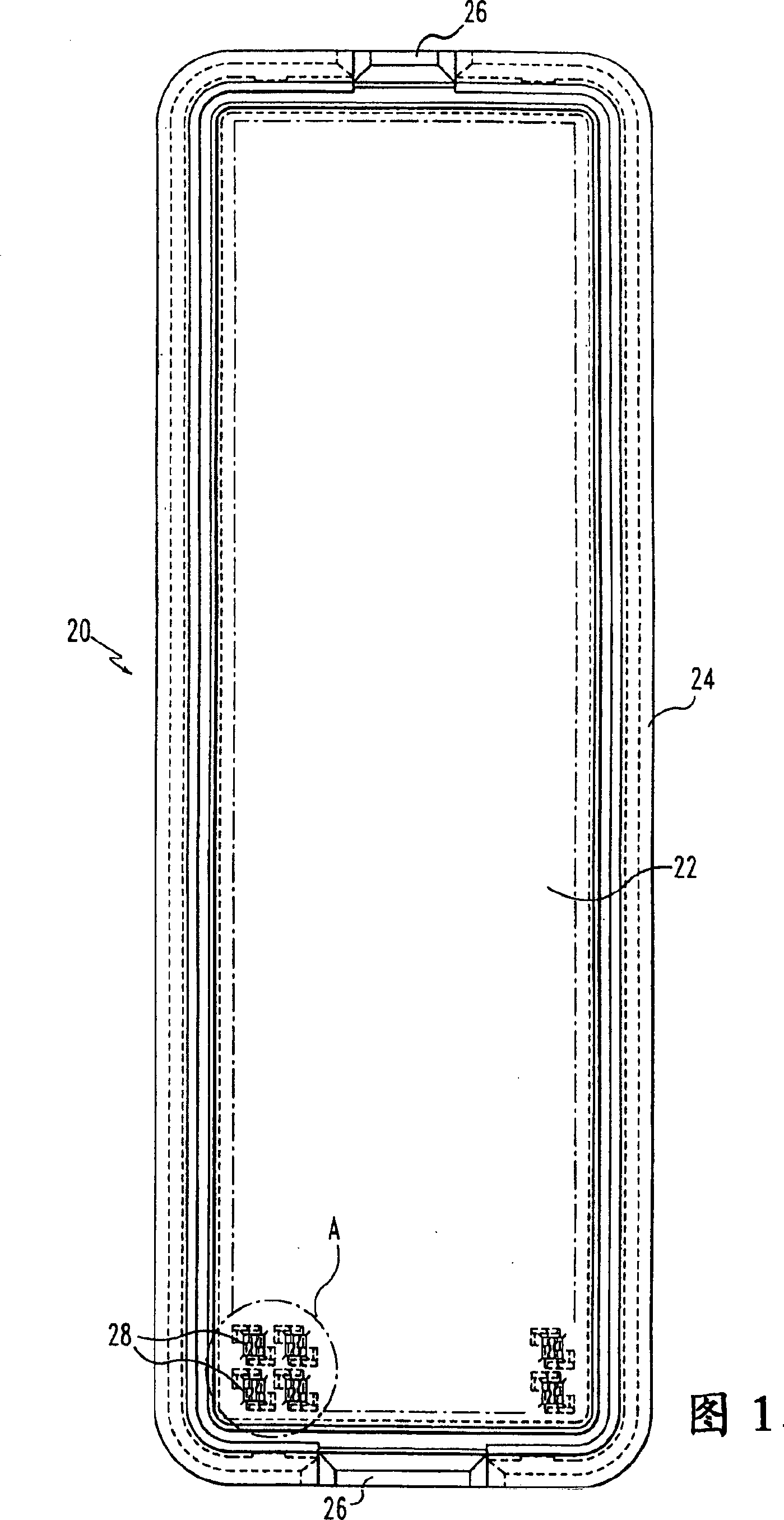
[0026] FIG. 1 shows a plug connector 20 having a connector body or housing which includes a substantially planar base 22 and a surrounding peripheral wall 24 . On each end wall there are polarization / alignment tabs 26 which stand upright from wall 24 to ensure that pin connector 20 mates with its mating female connector as hereinafter described. The connector body is preferably formed as a unitary, one-piece body by molding the insulating polymer. The polymer is preferably one that is resistant to SMT (Surface Mount Technology) reflow temperatures, such as liquid crystal polymers.
[0027] The pin connector 20 includes an array 28 of pin contact lugs retained on the connector body in a desired pattern, such as a two-dimensional matrix. For simplicity of the drawing, only a few lug positions are shown.
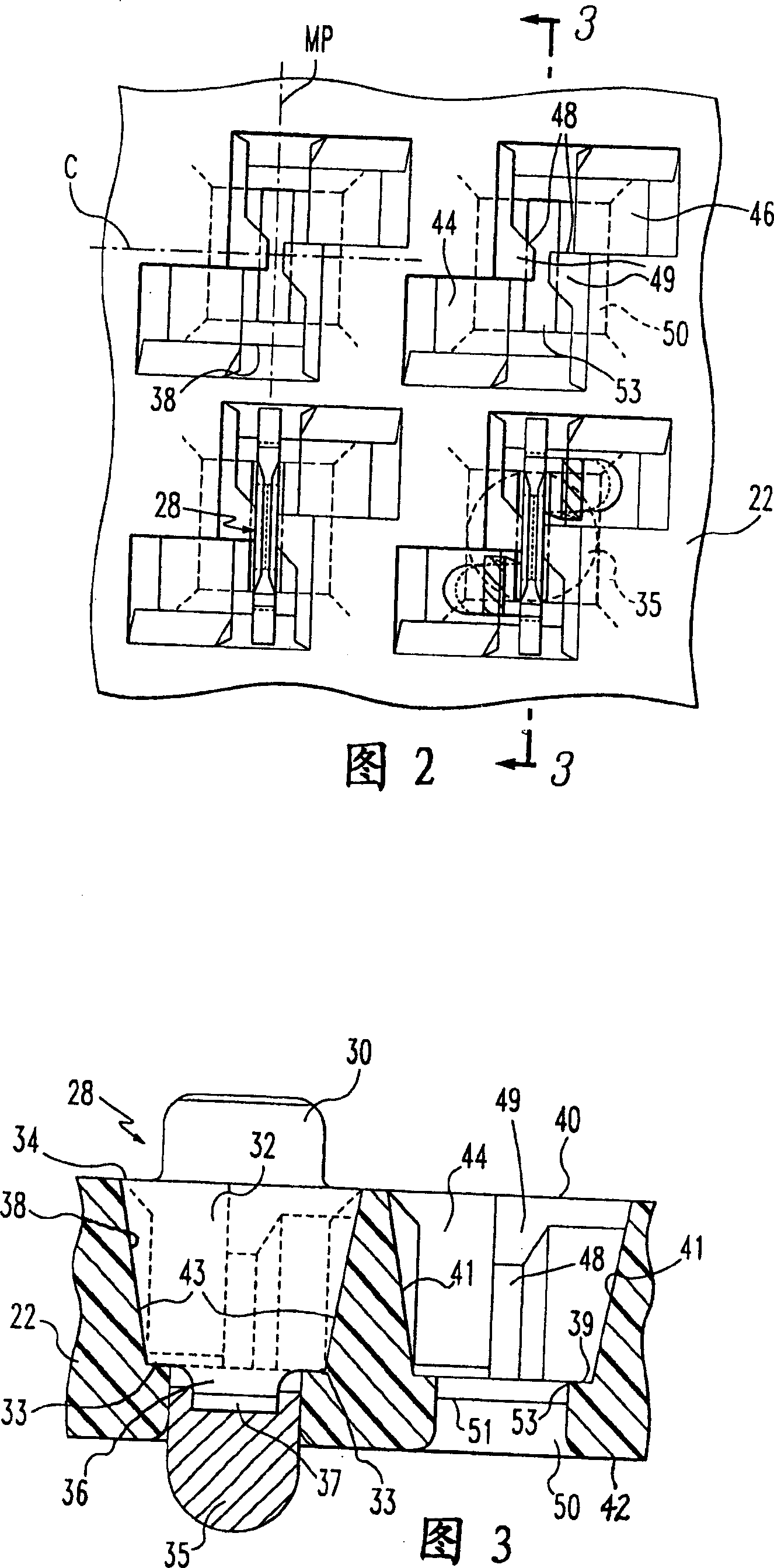
[0028] Referring to FIG. 3, each pin lug 28 includes a planar contact lug having a mating section 30 for mating with a receptacle contact lug 72 described hereinafter. The p...
PUM
 Abstract
Description
Claims
Application Information