
Apparatus for inner surface modification by plasma source ion implantation

A technology of plasma source and ion implantation, which is applied in the direction of ion implantation plating, metal material coating process, coating, etc., can solve the problems that cannot be used to treat the inner surface of pipe fittings, etc., and achieve a modified inner surface of tubular workpieces Uniformity, improve anti-corrosion and wear resistance, and improve efficiency

Inactive Publication Date: 2008-02-13
INST OF PHYSICS - CHINESE ACAD OF SCI
View PDF6 Cites 1 Cited by
  • Summary
  • Abstract
  • Description
  • Claims
  • Application Information

AI Technical Summary

Problems solved by technology

But at this time, directly using PSII technology to inject the inner surface of the tubular workpiece cannot be used to treat the inner surface of the pipe with a diameter-to-length ratio of less than 0.6.

Method used


Image

  • Apparatus for inner surface modification by plasma source ion implantation
  • Apparatus for inner surface modification by plasma source ion implantation

Examples


Embodiment Construction

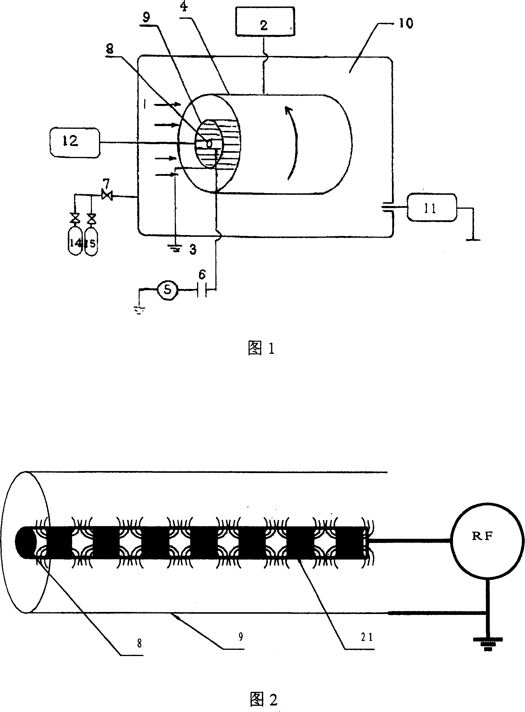
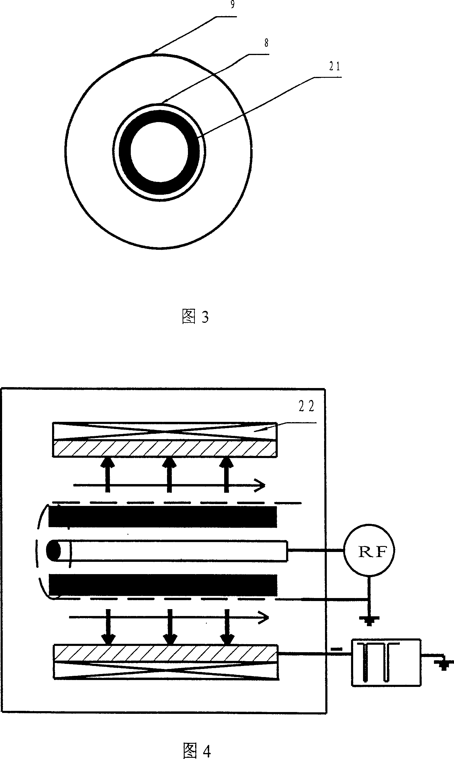
[0024] The plasma source ion implantation internal surface modification device of the present invention, as shown in FIG. 1, mainly includes a processing chamber 10 with a vacuum device 11, and the processing chamber 10 is connected to a working gas source argon cylinder 14 through a fine-tuning needle valve 7 And the nitrogen cylinder 15; in the processing chamber 10, the cylindrical electrode 8, the tubular electrode 9 and the tubular workpiece 4 are arranged coaxially from the inside out, and the columnar electrode 8 is placed in the center of the tubular workpiece 4, between the cylindrical electrode 8 and the tubular workpiece 4 A tubular electrode 9 composed of electrode wires uniformly distributed in the circumferential direction is set; the tubular electrode 9 and the cylindrical electrode 8 are connected to a radio frequency power supply 5, wherein the cylindrical electrode 8 is connected to the power electrode of the radio frequency power supply 5 through a DC blocking c...


PUM


Abstract

The invention relates to a device for inner surface modification by injecting plasma ion source, wherein: setting a tubular work-piece into a processing chamber, laying a columnar electrode and a tubular electrode allowing plasma diffusion in the tubular work-piece from inside to out side coaxially_ contacting the two electrodes with the radio frequency power supply, connecting a negative high tension supply between the tubular electrode and the tubular work-piece, also including a driving device capable of making relative rotation between tubular work-piece and tubular electrode; the tubular electrode is made up of electrode wires on the outer surface of tubular support, the electrode wires are in circumferential uniform distribution or screw-type distribution; the columnar electrode is a hollow tube with magnetic-irons in it; the tubular electrode is an interconnected hollow metal tube. the magnetic-irons are ring, and axially uniformly distributed with homopolarity opposition. The invention intensifies the sputtering of plasma to center electrode material by setting magnetic-irons in the tubular electrode, and improves the processing efficiency of tubular work-piece inner surface.

Description

Technical field [0001] The invention relates to a plasma source ion implantation technology, in particular to a plasma source ion implantation device for inner surface modification. Background technique [0002] At present, plasma source implantation (PS II) is a new material surface ion implantation technology, such as in the literature J. Appl. Phys. (Journal of Applied Phys.) Vol. 62 (1987) pages 4591-4596 by JR Conrad The article "Plasma source-implantation technique for surface modification of materials" by JLRadtke, RADodd, Frank J. Worzala, and Ngoc C. Tran introduces such a plasma source ion implantation technique. But at this time, the PSII technology can not be used to directly inject the inner surface of the tubular workpiece into the inner surface of the pipe with a diameter-to-length ratio of less than 0.6. In order to solve this problem, the applicant proposed a method for modifying the inner surface of tubular workpieces based on PS II technology in a Chinese inven...

Claims


Application Information

Patent Timeline
Patent Type & Authority Patents(China)
IPC IPC(8): C23C14/48
Inventor 杨思泽张谷令王久丽刘元富
Owner INST OF PHYSICS - CHINESE ACAD OF SCI
Learn More