
Laser surface processing device and method

A surface processing and optical device technology, applied in laser welding equipment, metal processing equipment, optics, etc., can solve the problems of low use efficiency and low service life of the laser source, and achieve the goal of improving efficiency, improving utilization, and prolonging service life. Effect

Inactive Publication Date: 2011-08-24
施政辉
View PDF6 Cites 7 Cited by
  • Summary
  • Abstract
  • Description
  • Claims
  • Application Information

AI Technical Summary

Problems solved by technology

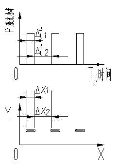
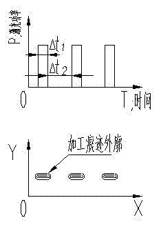
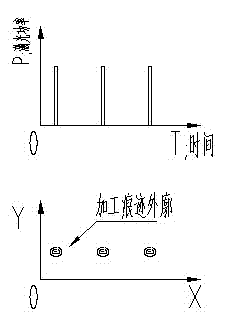
This creates a problem: see the figure below: figure 1 It is the laser path formed on the processing surface when the laser is turned off. Due to the thermal effect of the laser, it expands uniformly outward for a period of time. See figure 2 In the figure, the outline figure of the processing marks actually appearing on the processing surface is shown in figure 2 , we find that the points that appear are slender bars of appearance
The service life and utilization of the laser source are related to the cut-off frequency of the laser source; in order to pursue a relatively round or high-quality shape point, the laser needs to maintain a high cut-off frequency, which leads to the laser source having Lower service life and lower efficiency

Method used


Image

  • Laser surface processing device and method
  • Laser surface processing device and method
  • Laser surface processing device and method

Examples


Embodiment 1

[0034] Laser surface processing devices, such as Figure 4 As shown, it includes a laser source 5 that emits three laser beams, a spectroscopic device (N≥2) that splits each laser beam into N groups of laser beams distributed along the time axis and irradiated circularly, and a focusing optical device. The spectroscopic device includes a scanning optical device for forming 3-way laser beams into a circular scanning laser, and a catadioptric optical device for changing the direction of the circular scanning laser. The scanning optical device is specifically a rotating polygonal mirror 1; the catadioptric optical device is three mirrors 2 with N surfaces; the focusing optical device is an optical element that can adjust the position and can gather or diverge 3×N groups of laser light, Convex lens 3 is specifically selected as the optical element in this implementation. By adjusting the position adjustment mechanism inside the focusing optical device ( Figure 4 The position ad...

Embodiment 2

[0038] The laser surface processing device, this embodiment is basically the same as Embodiment 1, the difference is that the scanning optical device that forms the 3-way laser beam into the circular scanning laser in the beam splitting device does not use a rotating polygonal mirror, but a reciprocating swinging swing instead of a rotating polygonal mirror. Mirror, swing mirror is a reciprocating plane mirror, its working principle is as follows Figure 10 As shown, the reciprocating swing of the oscillating mirror 6 reflects the laser beam projected on the oscillating mirror 6 to form a laser scanning area with an included angle of θ.

[0039] In the laser surface processing device provided in this embodiment, under the condition that the focusing optical device remains fixed, the processing marks projected onto the surface of the workpiece 4 have Figure 11 As shown in the processing traces, the processing traces in each processing cycle have higher disorder compared with E...

Embodiment 3

[0041] Laser surface processing device, this implementation example is basically the same as Embodiment 1, the difference is that the optical element of the focusing optical device adopts such as Figure 12 The combined optical element 7 shown is composed of a plurality of optical elements.


PUM


Abstract

The invention relates to a laser processing technology for a surface of a workpiece, and discloses a laser surface processing device and method. M paths of laser beams transmitted by a laser source are split by a light splitting device to form M*N groups of lasers which are distributed along the time axis and radiate circularly; and the M*N groups of lasers are projected on the surface of the workpiece after changing the direction by virtue of a refractive-reflective optical device. In the invention, the continuous working state of the laser source can be guaranteed, the service life of the laser source is prolonged, the utilization rate of the laser source is improved, and simultaneously the efficiency of surface processing is also improved, wherein M is more than or equal to 1 and N is more than or equal to 2.

Description

technical field [0001] The present invention relates to the laser processing technology of workpiece surface, more specifically, relates to a kind of laser surface processing device and laser surface processing method. Background technique [0002] At present, there are more and more application fields of laser. There is a kind of laser processing field that is mainly based on the arrangement of points or holes, which is to extend these points or holes to an area according to a certain arrangement. If it is processed point by point, the efficiency of the laser emitted by the laser source is too low, so that it affects the application, and even in order to improve the efficiency, the quality or density of the laser processing point is reduced. In these application fields, the laser pulse working mode is usually used now. Since the processing point is disconnected, the disconnected area is in the off state for the laser, so the laser processing is an alternating process of on ...

Claims


Application Information

Patent Timeline
Patent Type & Authority Applications(China)
IPC IPC(8): B23K26/00B23K26/02G02B26/10G02B17/06G02B19/00G02B26/12B23K26/064B23K26/082B23K26/352
Inventor 张志杰
Owner 施政辉
Learn More