Ultrasonic apparatus and method for measuring the concentration and flow rate of gas

A technology of ultrasound, equipment, applied in the field of ultrasound equipment

Active Publication Date: 2008-03-12
TEIJIN LTD
View PDF4 Cites 1 Cited by
  • Summary
  • Abstract
  • Description
  • Claims
  • Application Information

AI Technical Summary

Problems solved by technology

However, hardware must be used to extract the received ultrasound, and complex signal processing is required to calculate the envelope curve from the extracted waveform

Method used


Image

  • Ultrasonic apparatus and method for measuring the concentration and flow rate of gas
  • Ultrasonic apparatus and method for measuring the concentration and flow rate of gas
  • Ultrasonic apparatus and method for measuring the concentration and flow rate of gas

Examples


Embodiment Construction

[0087] The best way to practice the invention

[0088] Preferred embodiments of the present invention are described below. In the embodiments described below, the sample gas consists of oxygen and nitrogen. However, measurable sample gases are not limited to gas samples of oxygen and nitrogen, and the present invention can also be applied to mixtures containing other gases.

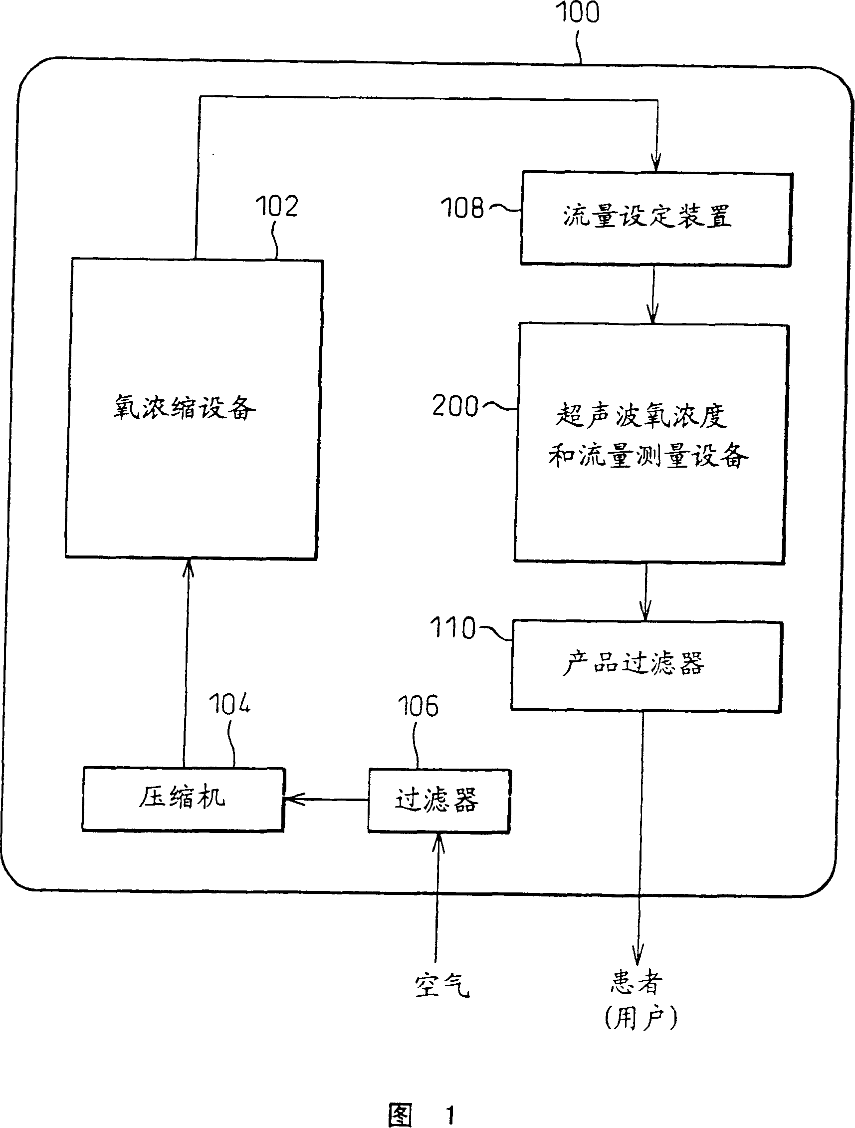
[0089] Figure 1 shows a schematic diagram of an oxygen concentrator system according to a preferred embodiment of the present invention, which has ultrasonic gas concentration and flow measurement equipment.

[0090] The plant 100 includes an oxygen enrichment plant 102 that produces oxygen-enriched gas by removing nitrogen from air provided by a compressor 104 through a filter 106 from outside the system. The oxygen-enriched gas generated by the oxygen concentrator 102 is supplied to the ultrasonic device 200 of the present invention through a flow setting device 108, such as a pressure reducing valve....


PUM


Abstract

The present invention provides an ultrasonic apparatus measures the concentration and flow rate of a sample gas by calculating a possible propagation time range on the basis of the gas temperature, determining whether or not the phases at which two first trigger signals, respectively generated on the basis of forward and backward waveforms of the ultrasonic waves, coincide with each other, processing the zero-cross signals so that the phases coincide with each other, obtaining reference zero-cross time instant by calculating mean value of the forward and backward zero-cross time instants, obtaining an ultrasonic reception point by subtracting an integral multiple of the cycle of the ultrasonic waves so that the results of the subtraction falls into a possible propagation time range and estimating the ultrasonic propagation time on the basis of the ultrasonic reception point.

Description

technical field [0001] The present invention relates to an ultrasonic device and method for determining the concentration of oxygen in a sample gas provided by an oxygen concentrator for medical purposes and the flow rate of the sample gas. Background technique [0002] It is well known that the propagation speed of ultrasonic waves in sample gas can be expressed as a function of sample gas concentration and temperature. Assuming that the average molecular weight of the sample gas is M and the temperature is T (K), the ultrasonic velocity C (m / sec) passing through the static sample gas is expressed as the following equation (1) [0003] C=(κRT / M) 1 / 2 ...(1) [0004] in, [0005] κ: ratio of molecular specific heat at constant volume to molecular specific heat at constant pressure [0006] R: gas constant [0007] Therefore, as long as the ultrasonic propagation velocity C (m / sec) passing through the sample gas and the temperature T (K) of the sample gas are measured, th...

Claims


Application Information

Patent Timeline
Patent Type & Authority Patents(China)
IPC IPC(8): G01F1/66G01N29/02G01N29/00
CPCG01N2291/02818G01N2291/02836G01N2291/02809G01N2291/02881
Inventor 藤本直登志
Owner TEIJIN LTD
Why Eureka
Try Eureka