Optical disk having pattern for tilt detection

A technology of tilt detection and optical disc, which is applied in the direction of optical recording/reproduction, digital signal error detection/correction, optical record carrier, etc., and can solve the problem of signal detection degradation and other problems

Inactive Publication Date: 2008-03-12
SAMSUNG ELECTRONICS CO LTD
View PDF3 Cites 1 Cited by
  • Summary
  • Abstract
  • Description
  • Claims
  • Application Information

AI Technical Summary

Problems solved by technology

Further, the degree of signal detection becomes degraded due to the existence of the detection signa

Method used


Image

  • Optical disk having pattern for tilt detection
  • Optical disk having pattern for tilt detection
  • Optical disk having pattern for tilt detection

Examples


Embodiment Construction

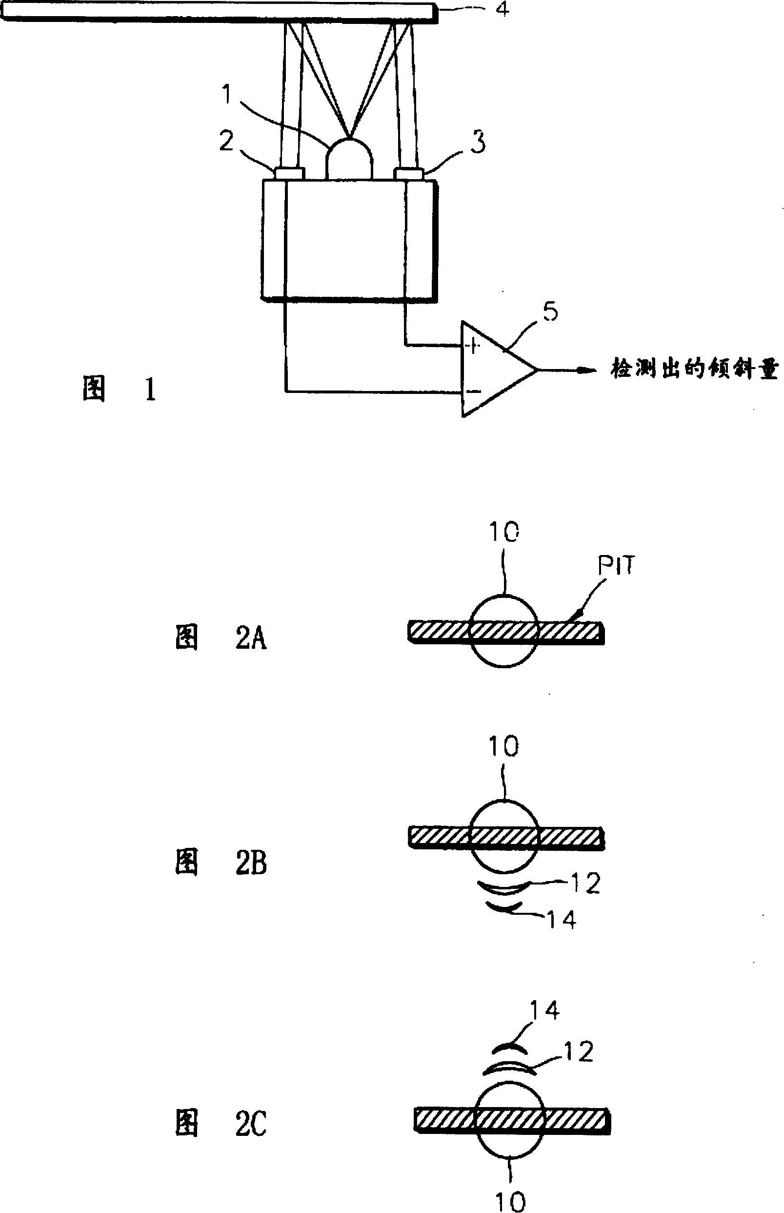
[0058] 2A and FIG. 2C are views showing the distribution of laser beams radiated onto the surface of an optical disc, wherein FIG. 2A shows a situation where no tilt occurs, FIG. 2B shows a situation where there is a downward tilt, and FIG. 2C shows a situation where there is an upward tilt. Case.

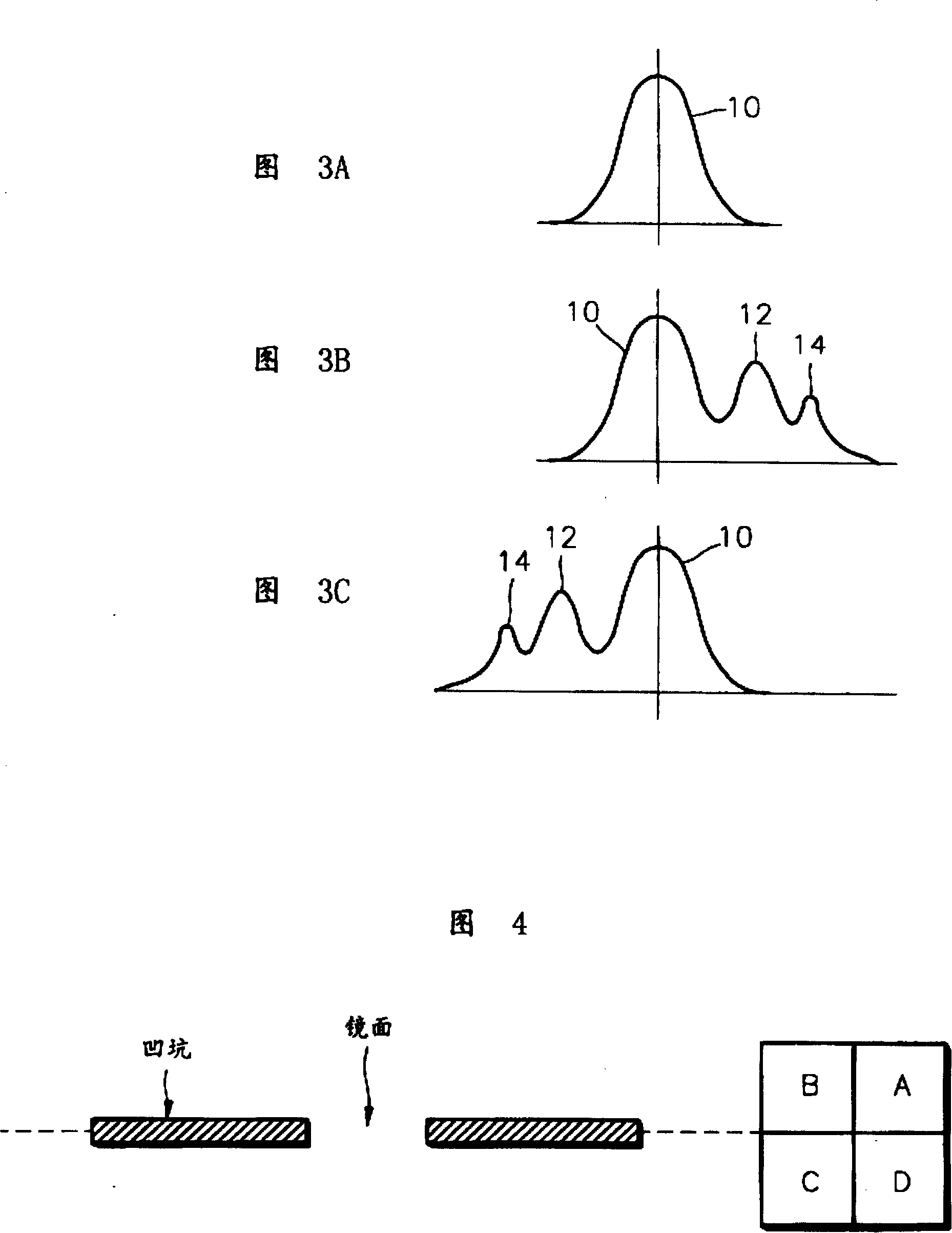
[0059] When no tilt occurs, the distribution of the laser beam forms a small circle, and the energy of the laser beam is concentrated to the center of the circle. The energy distribution in this case is shown in Figure 3A. In the absence of tilt, the distribution of the laser beam resembles a Gaussian distribution.

[0060] When the disc is tilted, the distribution of the laser beam expands, as opposed to the case where the disc is not tilted, as shown in Figures 2B and 2C, where the energy of the laser beam is diffused centrally and peripherally. That is, a main lobe 10 with maximum energy is created in the middle of the circle, while first side lobes 12 and second side lobes 14...


PUM


Abstract

An optical disk has a pattern for detecting an amount of a tilt of a disk. An optical disk on which a code train having a pit pattern or a mirror pattern is recorded on a concentrically or spirally formed track, wherein a tilt detection pattern having a predetermined code train is recorded at least in a partial area of the disk. Thus, a tilt of a disk can be detected by a common quadrant photodetector without an additional apparatus such as a photo coupler.

Description

technical field [0001] The present invention relates to optical discs for use in optical disc players, and more particularly, to optical discs having a pattern allowing detection of the degree of inclination of the disc. Background technique [0002] In compact disc (CD) players or digital video disc (DVD) players, the tilt of the disc is a major factor in signal reproduction degradation. In particular, when the aperture ratio of the objective lens increases as the density of the recording medium increases and the wavelength of the laser beam shortens, performance degradation due to tilt greatly increases. Correspondingly, correction of performance degradation due to inclination of the optical disc of the high-density recording medium becomes very important. [0003] To correct for signal degradation due to the tilt of the disc in the disc player, the spindle motor shaft, or the base plate on which the disc is placed or the optical pickup mechanism to pick up the signal is ...

Claims


Application Information

Patent Timeline
IPC IPC(8): G11B7/24G11B7/007G11B7/013G11B7/09G11B7/095G11B20/18
CPCG11B7/00745G11B7/0938G11B7/0956G11B7/24085G11B7/007G11B20/18
Inventor 郑种三李哲雨朴仁植
Owner SAMSUNG ELECTRONICS CO LTD
Why Eureka
Try Eureka