Check patentability & draft patents in minutes with Patsnap Eureka AI!

AC power supply permanent magnetic DC motor

A permanent magnet DC and AC power supply technology, applied in the direction of DC commutators, electrical components, electromechanical devices, etc., can solve problems such as limiting the application of DC motors

Inactive Publication Date: 2008-03-19
许晓华
View PDF2 Cites 0 Cited by
  • Summary
  • Abstract
  • Description
  • Claims
  • Application Information

AI Technical Summary

Problems solved by technology

Since there are only AC power supplies in many occasions, the application of DC motors is limited

Method used


Image

  • AC power supply permanent magnetic DC motor
  • AC power supply permanent magnetic DC motor
  • AC power supply permanent magnetic DC motor

Examples


Embodiment Construction

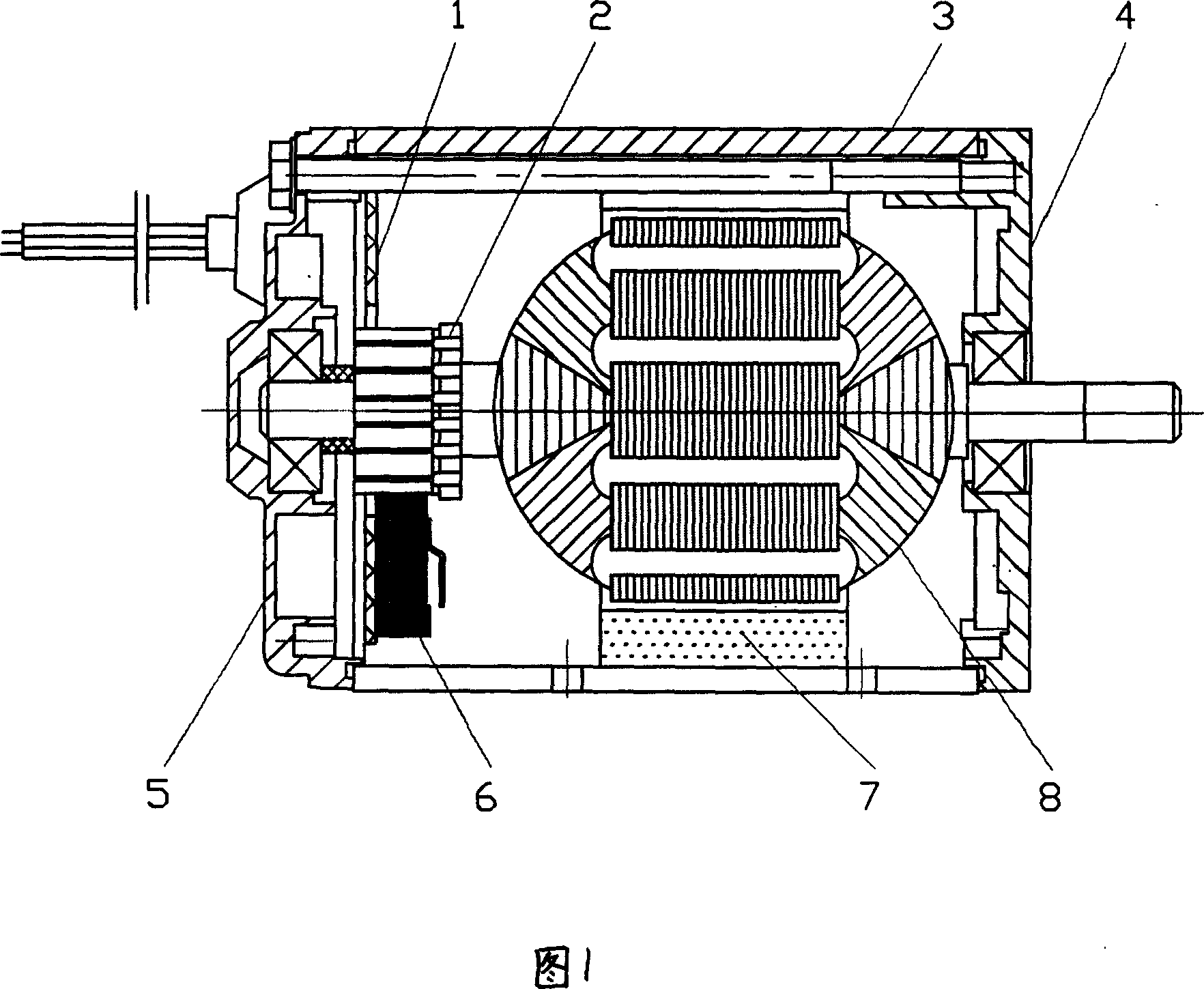
[0012] In the embodiment shown in Fig. 1, the body of the permanent magnet DC motor includes a front end cover 4, a casing 3, a magnetic steel 7, a rotor 8, a commutator 2 and a rear end cover 5 with a carbon brush structure 6, in the described A front circuit board 1 for rectification and filtering is arranged on the rear end cover 5 .

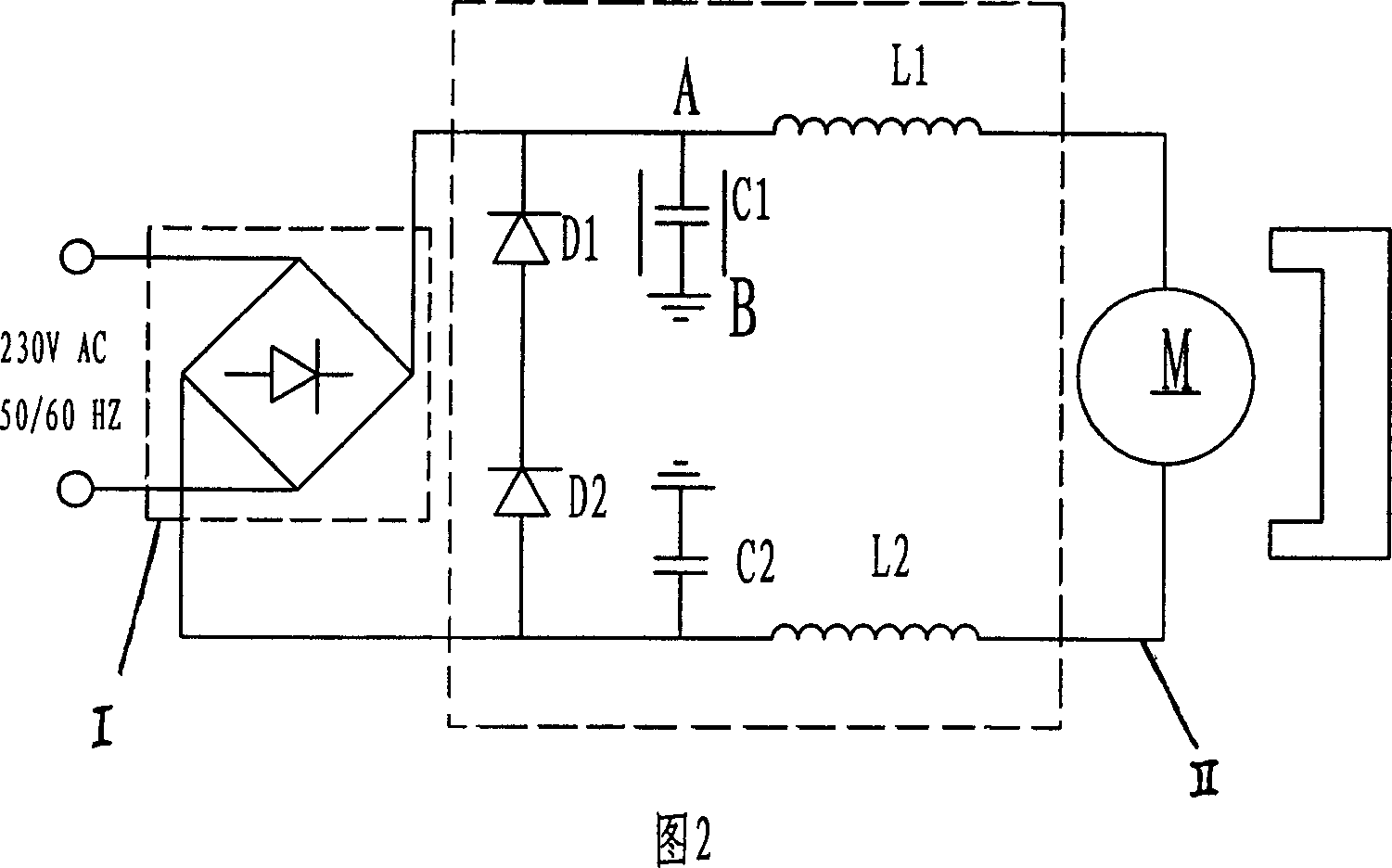
[0013] Referring to Fig. 2, described rectification circuit I adopts bridge rectification circuit. The filter circuit includes a pair of inductors L1, L2 and a pair of grounding capacitors C1, C2, the inductor L1 is connected in series between the output end of the rectifier circuit and one end of the motor winding M, and the inductor L2 is connected in series between the rectifier Between the other output end of the circuit and the other end of the motor winding M; one end of the pair of grounding capacitors C1 and C2 are respectively connected to the two output terminals of the rectification circuit, and the other end is grounded. A pair o...


PUM


Abstract

The invention discloses an AC power supply direct current dynamo which comprises a permanent-magnet direct current dynamo machine, wherein is also comprises a front end circuit equipped with commutating filtration for commutating AC supply into DC supply, and the terminal voltages of the armature are held stationary through a filtering circuit, thus enabling the permanent-magnet direct current dynamo to operate in AC environment directly.

Description

technical field [0001] The invention relates to the field of motors, in particular to an AC-powered permanent magnet DC motor. Background technique [0002] Permanent magnet DC motors are widely used due to their simple structure, low price, convenient speed regulation and low noise. The existing permanent magnet DC consists of a front cover, a casing, a magnet, a rotor, a commutator and a rear cover with a carbon brush structure. Its working principle is: when the coil is energized, its effective side is at the One pole, such as N pole, at this time, the effective side will be subjected to an electromagnetic force, under the action of the electromagnetic force, the rotor will rotate; when the rotor rotates until the effective side is at the other pole of the magnetic steel, that is At the S pole, due to the mutual cooperation between the moving commutator and the stationary carbon brush, the direction of the current flowing through the effective side is opposite. The elec...

Claims


Application Information

Patent Timeline
Patent Type & Authority Patents(China)
IPC IPC(8): H02K23/66H02K11/00H02K11/04
Inventor 许晓华马巧芬张巧巧
Owner 许晓华
Features
  • R&D
  • Intellectual Property
  • Life Sciences
  • Materials
  • Tech Scout
  • Unparalleled Data Quality
  • Higher Quality Content
  • 60% Fewer Hallucinations
Learn More