Three-dimensional sequential effect maximization method for multi-stage turbomachine

A turbine and timing technology, applied in the direction of blade support components, mechanical equipment, engine components, etc., can solve the problems of not being able to maximize the use of two-dimensional timing, and achieve the effects of engineering practicality, efficiency improvement, and simple methods

Inactive Publication Date: 2008-03-26
青岛中科方舟航空科技有限公司
View PDF1 Cites 0 Cited by
  • Summary
  • Abstract
  • Description
  • Claims
  • Application Information

AI Technical Summary

Problems solved by technology

[0005] The purpose of the present invention is to overcome the problem that the larger benefits of two-dimensional time series cannot be brought into full play when the (three-dimensional) time series effect is applied in engineering practice, and to provide a method for maximizing the benefits of three-dimensional time series for multi-stage turbines

Method used


Image

  • Three-dimensional sequential effect maximization method for multi-stage turbomachine
  • Three-dimensional sequential effect maximization method for multi-stage turbomachine
  • Three-dimensional sequential effect maximization method for multi-stage turbomachine

Examples


Embodiment Construction

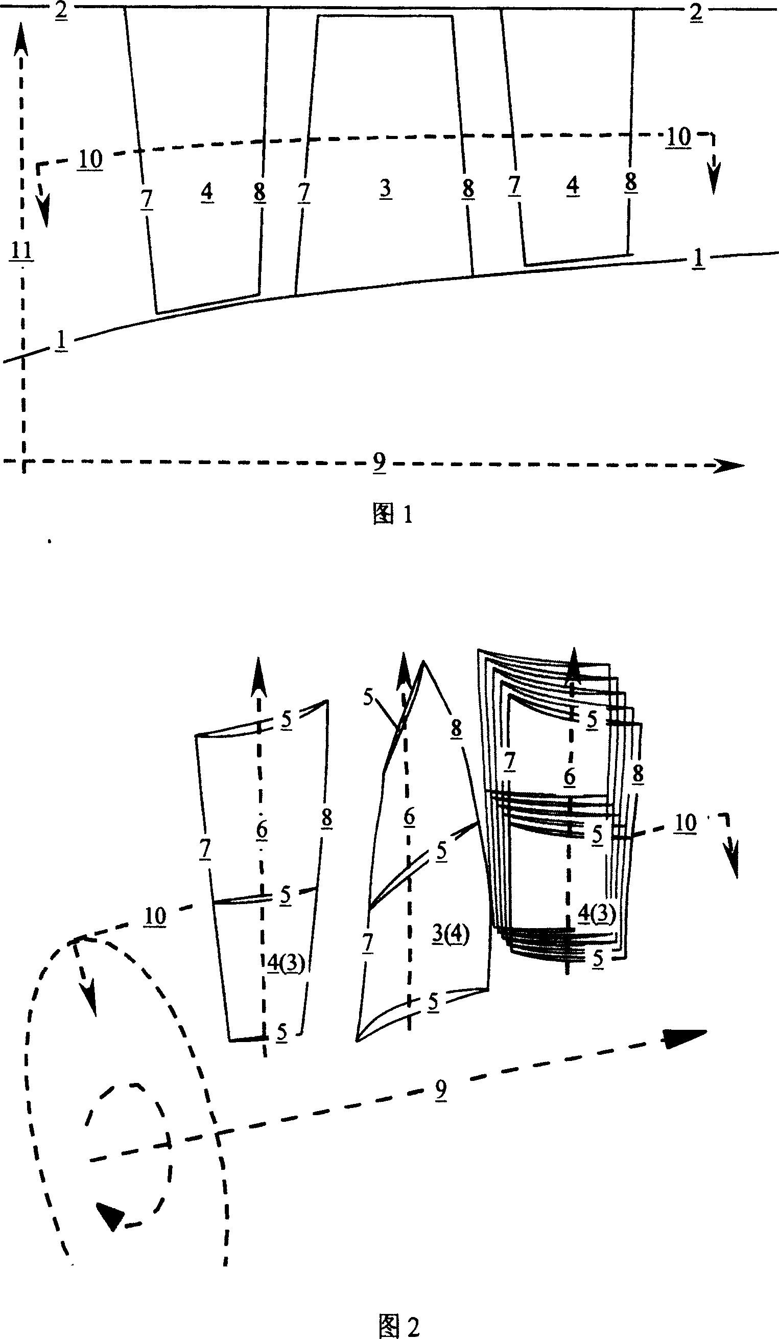
[0034] It should be noted that the same numbers in the drawings are used to represent the same characteristics, and some numbers have an underline to indicate that the position of the number is exactly the part to be represented.

[0035] The present invention will be further described in detail below in conjunction with the drawings and specific embodiments:

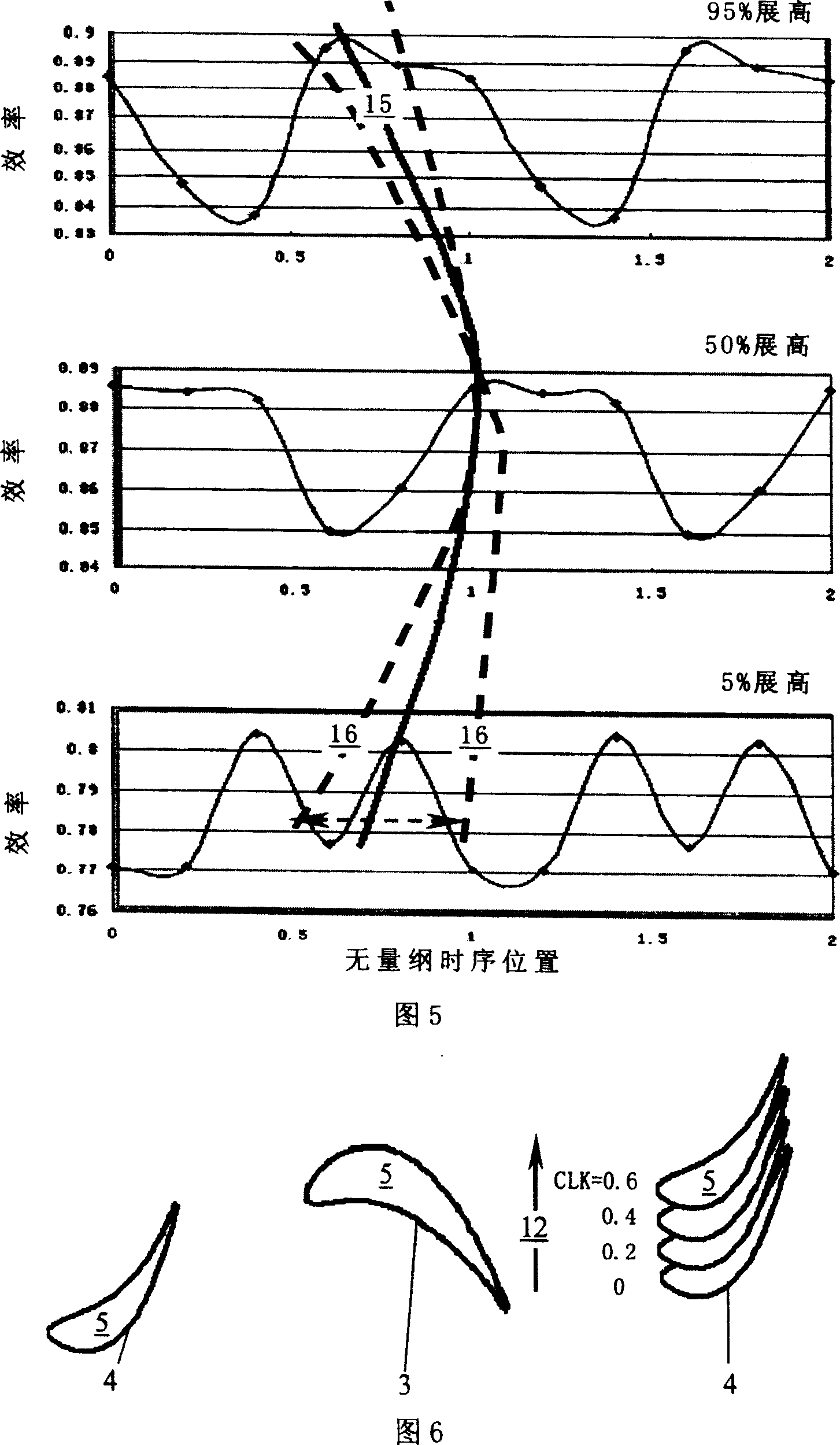
[0036] Referring to Figure 6, a certain 1.5-stage (static / rotation / static form, three rows of blades) axial flow turbine blades, in the process of re-stacking to achieve the maximum three-dimensional timing goal, includes the following steps:

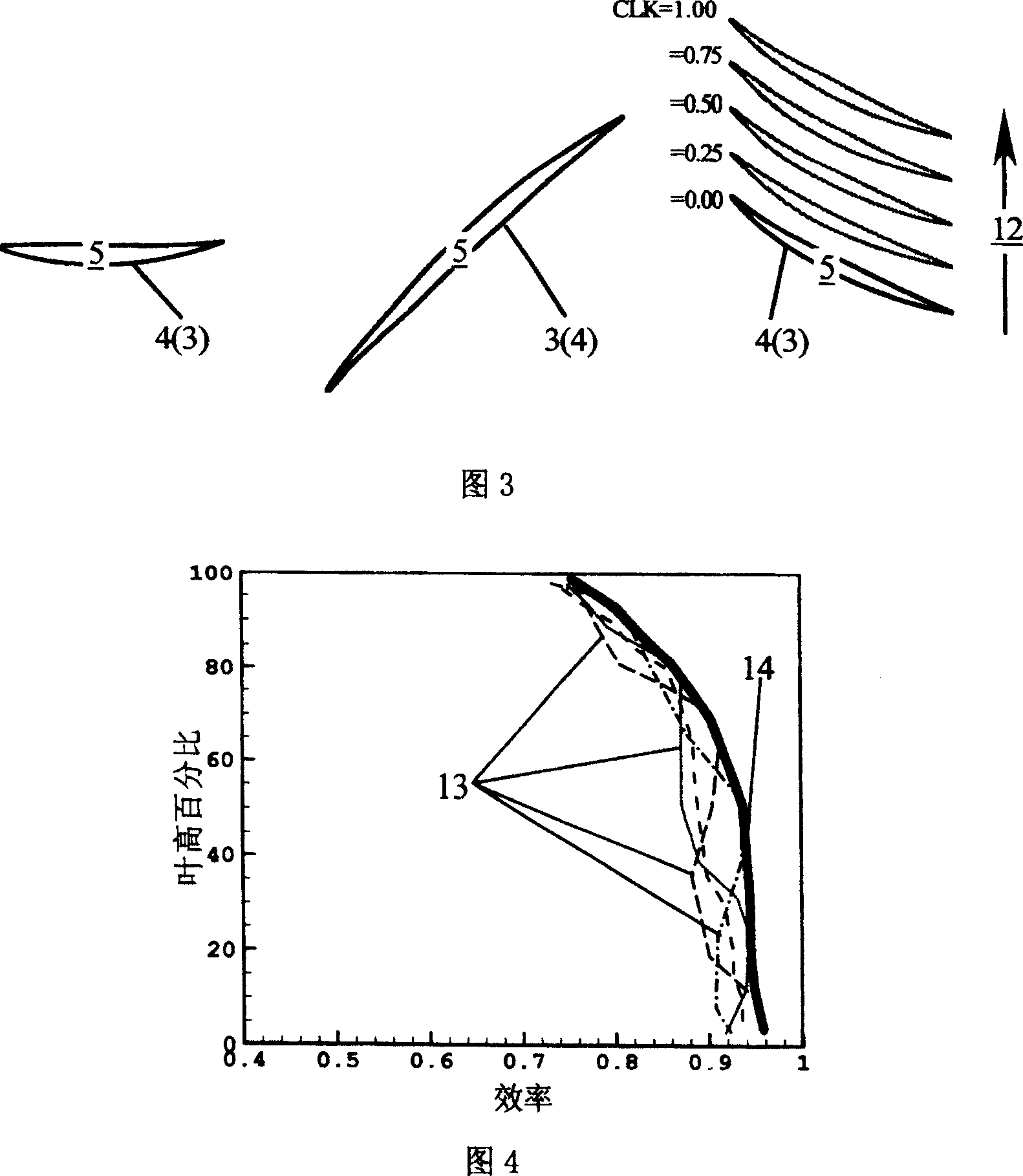
[0037] 1) Accurate unsteady flow field time for a multi-stage turbine with three-row blade combination at 5 time series positions 0, 0.2, 0.4, 0.6, 0.8 (with the dimensionless value of the grid pitch, Figure 6 shows a certain spanwise section) simulation;

[0038] 2) Analyze the time-average efficiency of each spanwise section of the multi-stage turbine in each sequence position in a...


PUM


Abstract

A method for maximizing the 3D time sequence effect of multi-stage impeller engine includes such steps as accurately simulating the transient flowing field time at multiple time sequence positions, analyzing the distribution of time average efficiency at each time sequence position in a time sequence period, linking the maximal time sequence effect points of each characteristic cross-section, determining the target edge profile match combination, accurately simulating the 3D transient flow time for each group of edge profile match combinations, finding out the result of time average effect, drawing a contour line of each group of edge profile match combination by using SH and ST as variables, choosing the highest point of time average effect, and re-integrating to generate vane.

Description

Technical field [0001] The invention relates to a multi-stage impeller, in particular to a method for maximizing the benefits of a three-dimensional time series for a multi-stage impeller. Background technique [0002] The well-known multi-stage impeller is an important component widely used in aviation, aerospace, navigation, energy, chemical industry and other fields. As shown in Figure 1, the hub 1, the casing 2 and the multiple blade rows enclosed by a distance The blade includes a rotating blade 3 rotating around a shaft 9 and a stationary blade 4 fixed on the casing 2. As shown in Figure 2, all blades are stacked by the element cascade 5 along the stacking line 6 in the spanwise direction. The foremost and the last part of the element cascade 5 are stacked to form the leading edge 7 and the trailing edge 8 of the blade. , As shown in Figures 1 and 2, the pressure of the working fluid gas is increased (compressor) or decreased (turbine) after passing through the above-mentio...

Claims


Application Information

Patent Timeline
Patent Type & Authority Patents(China)
IPC IPC(8): F01D5/14F01D9/02G06F17/50
Inventor 季路成
Owner 青岛中科方舟航空科技有限公司
Why Eureka
Try Eureka