

Personal care apparatus with an automatically pivotable head part
A technology for personal care and head parts, applied in metal processing and other directions, can solve problems such as different hair lengths, and achieve the effect of simple and convenient operation
- Summary
- Abstract
- Description
- Claims
- Application Information
AI Technical Summary
Problems solved by technology
Method used
Image

Examples
Embodiment Construction
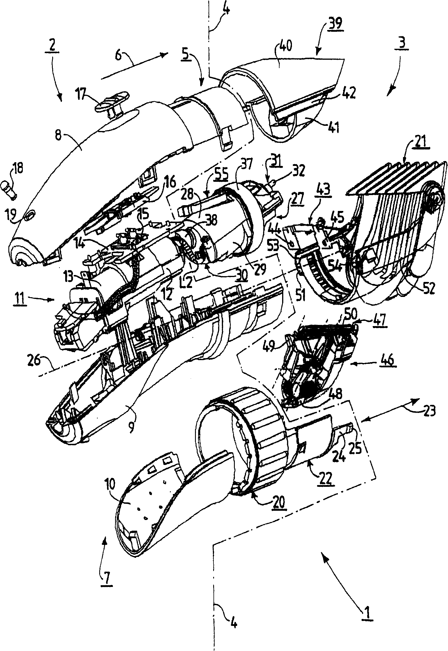
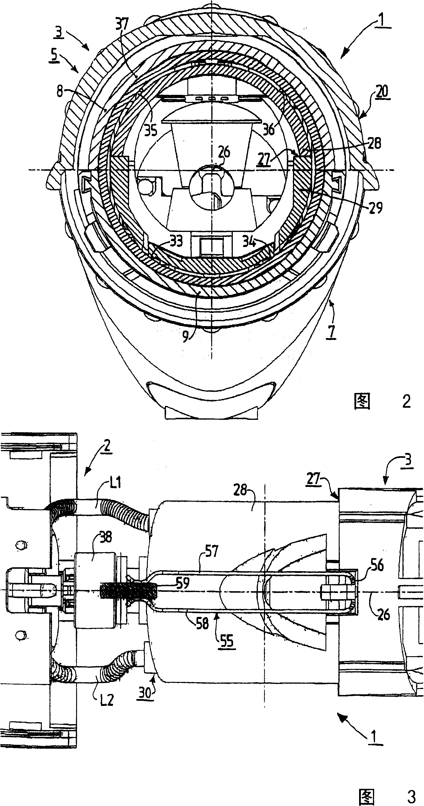
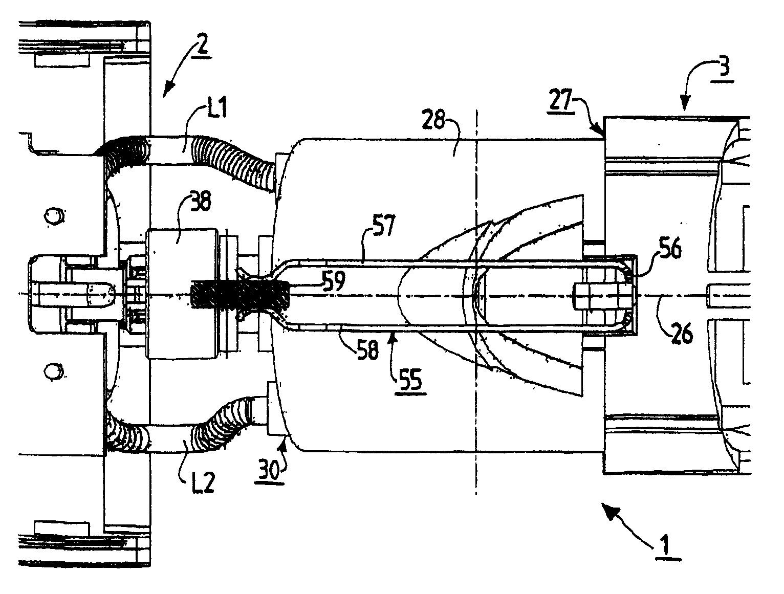
[0017] figure 1 ~ 3 represents a hair clipper 1 as a personal care appliance. The hair clipper 1 has a main part 2 and a head part 3 . The boundary between main part 2 and head part 3 is at figure 1 It is schematically indicated by the dotted line 4.
[0018] The main part 2 is designed to be held in the hand (not shown). When thus held in the hand, the region 5 of the main part 2 adjacent to the head part 3 protrudes from the hand in the protruding direction 6 indicated by the arrow. The main part 2 has a housing 7 . Essentially, the housing 7 comprises a housing top section 8 and a housing bottom section 9 as well as a cover part 10 connected to the housing bottom section 9 . Housing 7 houses a power supply device 11 for supplying electric power to the motor. The power supply unit 11 has a battery holder 12 in which, in this embodiment, a rechargeable battery 13 is securely held. A printed circuit board 14 is connected to the battery rack 12, and a switch 15 is instal...
PUM
 Abstract
Description
Claims
Application Information