Solid electrolytic capacitor and its manufacture method
A technology of solid electrolysis and capacitors, applied in solid electrolytic capacitors, electrolytic capacitors, capacitors, etc., to achieve the effect of improving the equivalent series resistance characteristics, stable welding operation, excellent bonding strength and reliability
- Summary
- Abstract
- Description
- Claims
- Application Information
AI Technical Summary
Problems solved by technology
Method used
Image
Examples
Embodiment approach 1
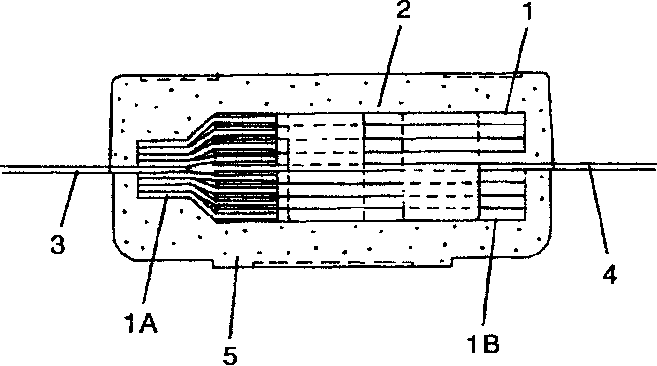
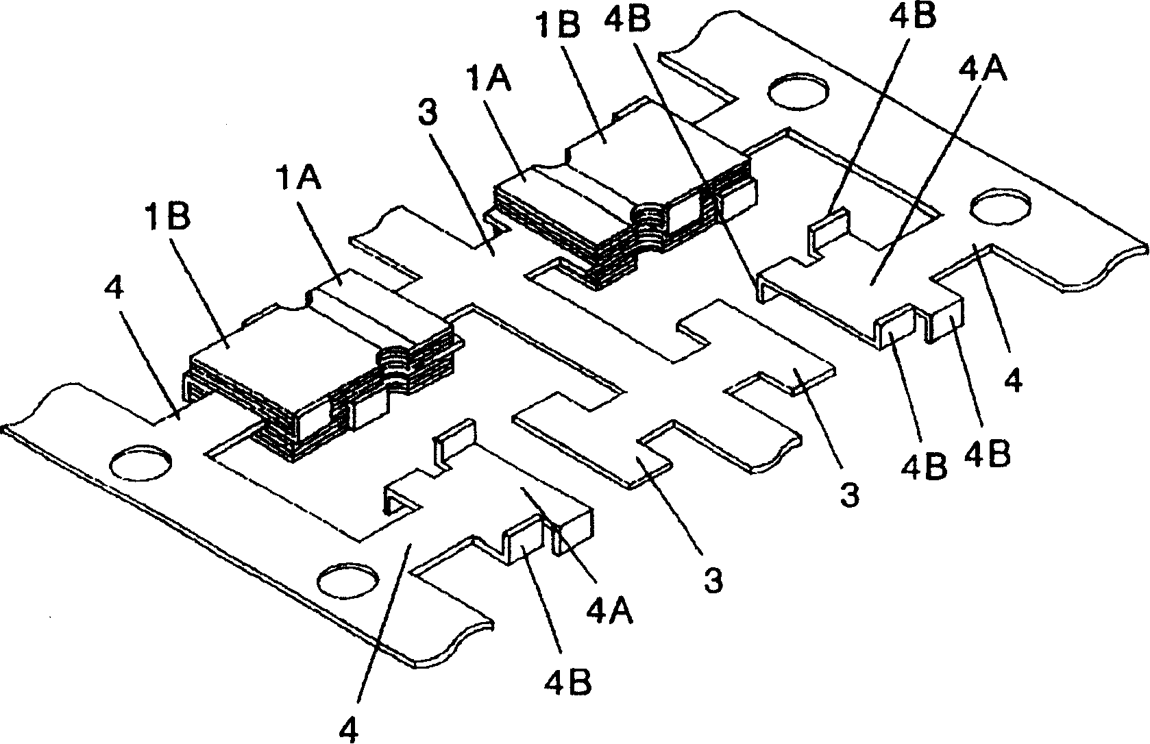
[0076] Mainly used below figure 1 with figure 2 Embodiment 1 will be described.
[0077] Capacitor element (hereinafter referred to as element) 1 separates the anode body composed of valve metal, that is, aluminum foil, into an anode part 1A and a cathode part, and is composed of a dielectric oxide film layer and a solid electrolyte layer formed by sequentially laminating on the surface of the cathode part 1B. layer, cathode tube (not shown).
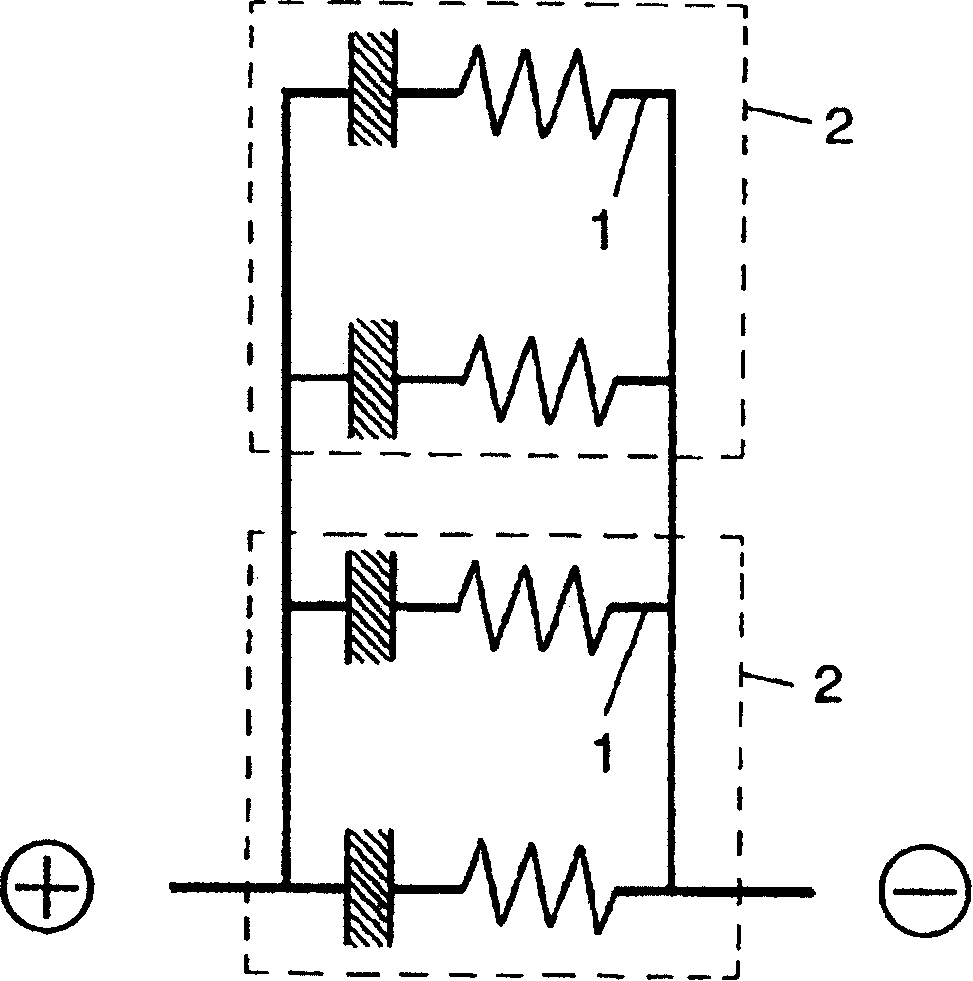
[0078] A capacitor element stack (hereinafter referred to as a stack) 2 is connected to an anode lead frame 3 and a cathode lead frame 4 after stacking a plurality of elements 1 . This structure will be described in more detail below. The anode part 1A of the element 1 is arranged on the front and back of the anode lead frame 3, and the cathode part 1B is arranged on the front and back of the cathode lead frame, respectively, and then stacked one by one. Next, the respective anode parts 1A are integrally bonded to the anode lead fr...
Embodiment approach 2
[0094] Embodiment 2 differs from Embodiment 1 in the shapes of the anode lead frame and the cathode lead frame, but is the same as Embodiment 1 except that. use below Figure 4 with Figure 5 Only the different parts are described.
[0095] A plurality of capacitive element parts 1A are disposed on one surface of the anode lead frame 6 and stacked one by one, and a plurality of cathode parts 1B are disposed on the front and back of the cathode lead frame 7 and stacked one by one. Each anode part 1A is integrally joined to each anode lead frame 61 by laser welding. In addition, the respective cathode portions are electrically bonded integrally at the connection portion 7B provided on the cathode lead frame 7 on the side surface in the thickness direction of the capacitor element 1 through conductive silver paste (not shown). In addition, the connecting portion 7B is formed in advance by bending a part of both ends of the planar portion 7A of the cathode lead frame 7 . In ad...
Embodiment approach 3
[0098] This third embodiment is an example in which the shape of the cathode lead frame in the above-mentioned embodiment 1 is different, and the configuration is the same as that of the first embodiment except that, and the following uses Image 6 , Figure 7 Only the different parts are described.
[0099]Cathode lead frame 8 has connection portion 8A and holding portion 8B formed by bending a part of cathode lead frame 8 .
[0100] The connecting portion 8A is formed so as to be located on the opposite side of the anode portion 1A of the capacitor element stack 2 . Then, the respective cathode portions 1B of the capacitor element 1 are integrally connected on the side surfaces in the thickness direction of the capacitor element 1 through the conductive silver paste 9 . In addition, the holding portion 8B holds the upper and lower surfaces of the capacitor element stack 2 .
[0101] The solid electrolytic capacitor in the third embodiment configured in this way has the pe...
PUM
 Abstract
Description
Claims
Application Information
 - R&D
- Intellectual Property
- Life Sciences
- Materials
- Tech Scout
- Unparalleled Data Quality
- Higher Quality Content
- 60% Fewer Hallucinations
Browse by: Latest US Patents, China's latest patents, Technical Efficacy Thesaurus, Application Domain, Technology Topic, Popular Technical Reports.
© 2025 PatSnap. All rights reserved.Legal|Privacy policy|Modern Slavery Act Transparency Statement|Sitemap|About US| Contact US: help@patsnap.com


