SAW filter

A surface acoustic wave and filter technology, applied to electrical components, impedance networks, etc., can solve problems such as lack of flatness of passband characteristics, steep frequency band characteristics, etc.

Inactive Publication Date: 2008-05-07
SKYWORKS PANASONIC FILTER SOLUTIONS JAPAN
View PDF3 Cites 0 Cited by
  • Summary
  • Abstract
  • Description
  • Claims
  • Application Information

AI Technical Summary

Problems solved by technology

The above-mentioned 2-channel filter can obtain a small SAW filter with steep frequency band characteristics, but there is a problem that the characteristics in the passband lack flatness

Method used


Image

  • SAW filter
  • SAW filter
  • SAW filter

Examples


Embodiment 1

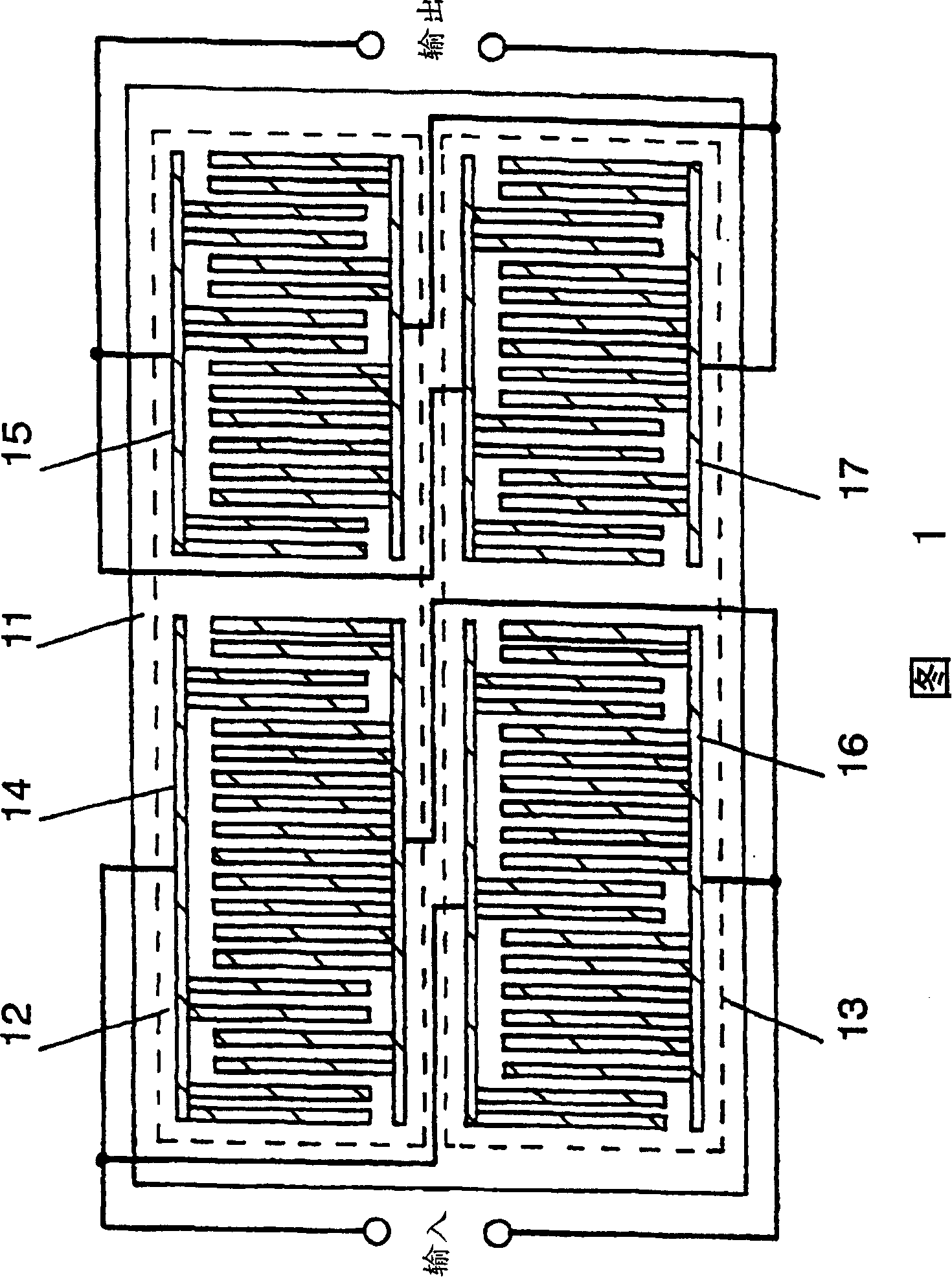
[0018] FIG. 1 is a top view of a SAW filter in Embodiment 1 of the present invention. As shown in FIG. 1 , the first filter track 12 and the second filter track 13 are configured to be connected in parallel on the piezoelectric substrate 11 formed by using a Y-cut crystal substrate rotated at 28° to 42°. The first filter track 12 is formed by an input IDT electrode 14 and an output IDT electrode 15 . Likewise, the second filter track 13 is formed by an input IDT electrode 16 and an output IDT electrode 17 .

[0019] Furthermore, the input IDT electrode 14 of the first filter track 12 and the input IDT electrode 16 of the second filter track 13 are connected in parallel. Likewise, the output IDT electrode 15 of the first filter track 12 and the output IDT electrode 17 of the second filter track 13 are connected in parallel.

[0020] Next, the operation of the SAW filter constructed as described above will be described.

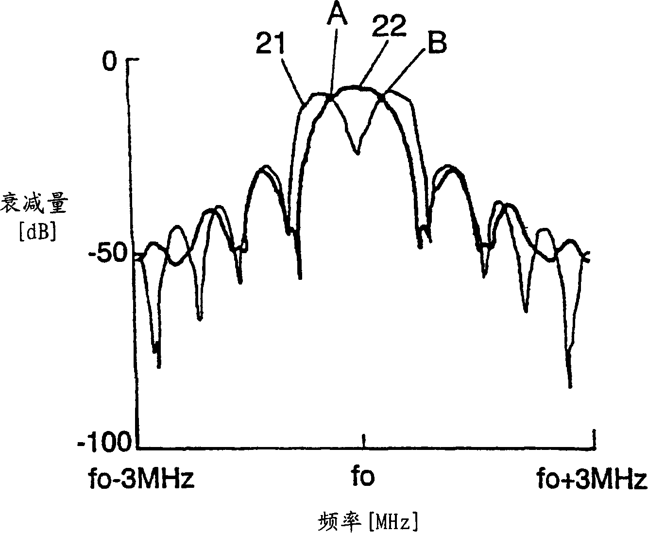
[0021] Figure 2A The amplitude characteristic 21 of t...

Embodiment 2

[0033] Fig. 3 is a plan view of the SAW filter in this embodiment. The SAW filter of this embodiment is the same as that of Embodiment 1, and is a kind of first filter channel 32 and second filter channel 33 with input and output IDT electrodes 34, 35, 36, 37 formed on a piezoelectric substrate 31. SAW filter. Also, the amplitude and phase characteristics of the first and second filter tracks 32, 33 are the same as in the first embodiment.

[0034] The difference from Example 1 is that unidirectional electrodes called EWC-SPUDT (Electrode Width Controlled Single Phase Unidirectional Transducer) are used as electrodes 34 , 35 , 36 , 37 . Specifically, when the electrodes 34, 35, 36, and 37 are divided according to the wavelength λ of the surface acoustic wave, one electrode finger with a width of λ / 4 and two electrode fingers with a width of λ / 8 are provided so that there are three electrode fingers in total. . In FIG. 3, the input IDT electrodes 34, 36 are formed to have ri...

Embodiment 3

[0039] FIG. 4 is a plan view of the SAW filter in Embodiment 3. FIG.

[0040] In this embodiment, the input and output IDT electrodes 44, 45, 46 and 47 that constitute the first filter channel 42 and the second filter channel 43 formed on the piezoelectric substrate 41 are made into electrodes called R-SPUDT (resonant SPUDT) constitute. The electrode structure is the same as that of Embodiment 2, and when the electrodes 44, 45, 46, and 47 are distinguished by the wavelength λ of the surface acoustic wave, there are one electrode finger with a width of λ / 4 and two electrode fingers with a width of λ / 8. Three electrodes refer to the area. Also, the amplitude and phase characteristics of the first and second filter tracks 42, 43 are the same as those of the first embodiment.

[0041] Figure 5 In , the arrows indicate the directivity of the regions A, B, and C framed by dotted lines. Regions A and C impart unidirectionality in the right orientation of the drawing, while regio...


PUM


Abstract

A SAW filter comprising a piezoelectric substrate and at least two filter tracks formed on the substrate, each having at least two IDT electrodes for input and output. The two filter tracks have substantially the same phase within a pass band, while it is substantially inverse-phased outside the pass band. For realizing the above-described conditions, input IDT electrode of one filter track is connected in parallel with input IDT electrode of the other filter track, while output IDT electrode of one filter track is connected in parallel with output IDT electrode of the other filter track. Furthermore, frequency values of said two filter tracks substantially coincide at a point 3dB lower from the peak transfer function value. Thus the above-configured SAW filter of the present invention is smaller in the overall size and offers a broad pass band and a steep attenuation characteristic.

Description

technical field [0001] The invention relates to a surface acoustic wave filter used in high frequency circuits, intermediate frequency circuits and the like of wireless communication equipment. Background technique [0002] For the IF (intermediate frequency) filter used in the CDMA mobile phone that has been paid attention to in recent years, a relatively wide passband is required, and the flatness of the phase characteristic in the passband is important. It is suitable to use independently designed amplitude characteristics and A transverse surface acoustic wave filter with phase characteristics (hereinafter referred to as a SAW filter). [0003] A transverse SAW filter using a conventional unidirectional electrode will be described below. [0004] Fig. 30 is a plan view of a transverse SAW filter using a conventional unidirectional electrode. In FIG. 30 , by forming input and output interdigital transducer electrodes (hereinafter referred to as IDT electrodes) on a sing...

Claims


Application Information

Patent Timeline
Patent Type & Authority Patents(China)
IPC IPC(8): H03H9/64H03H9/00H03H9/145
CPCH03H9/14538H03H9/14552H03H9/14505H03H9/14529H03H9/6433H03H9/0076H03H9/02637
Inventor 都筑茂井垣努松波贤西村和纪中村弘幸山田辙
Owner SKYWORKS PANASONIC FILTER SOLUTIONS JAPAN
Why Eureka
Try Eureka