
Muffler device

A technology of a muffler and a main body, which is applied in the field of muffler devices, can solve problems such as reducing exhaust gas emission performance, and achieve the effects of improving emission performance, improving corrosion resistance and appearance quality, and improving output.

Inactive Publication Date: 2008-05-14
HONDA MOTOR CO LTD
View PDF6 Cites 0 Cited by
  • Summary
  • Abstract
  • Description
  • Claims
  • Application Information

AI Technical Summary

Problems solved by technology

[0004] In recent years, attention has been paid to downsizing and weight reduction of the vehicle body and reduction of exhaust noise. For this reason, when it is necessary to reduce the size of the muffler body and improve the noise reduction performance, the adoption of the above structure will reduce the exhaust gas emission performance.

Method used


Image

  • Muffler device
  • Muffler device
  • Muffler device

Examples


Embodiment Construction

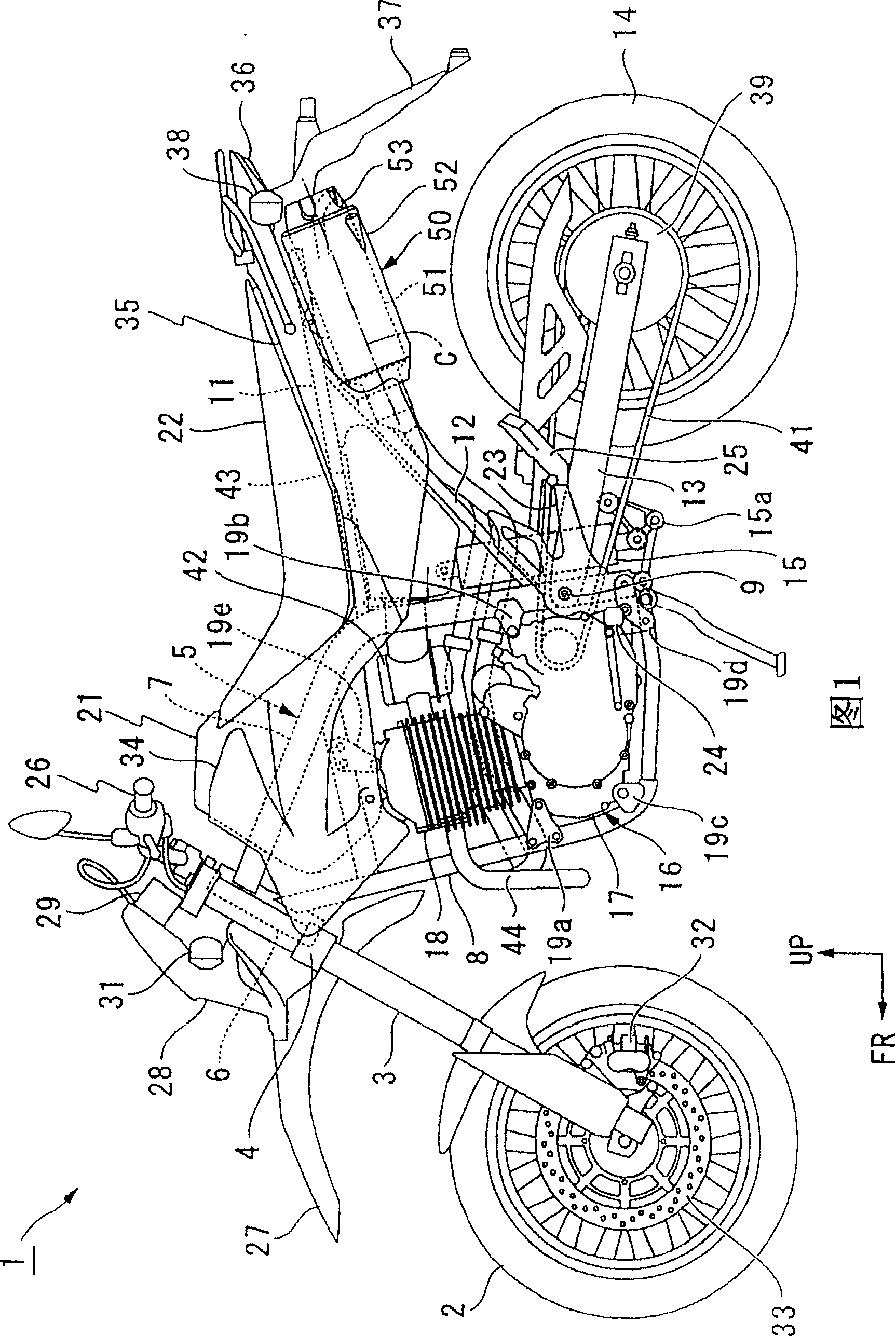
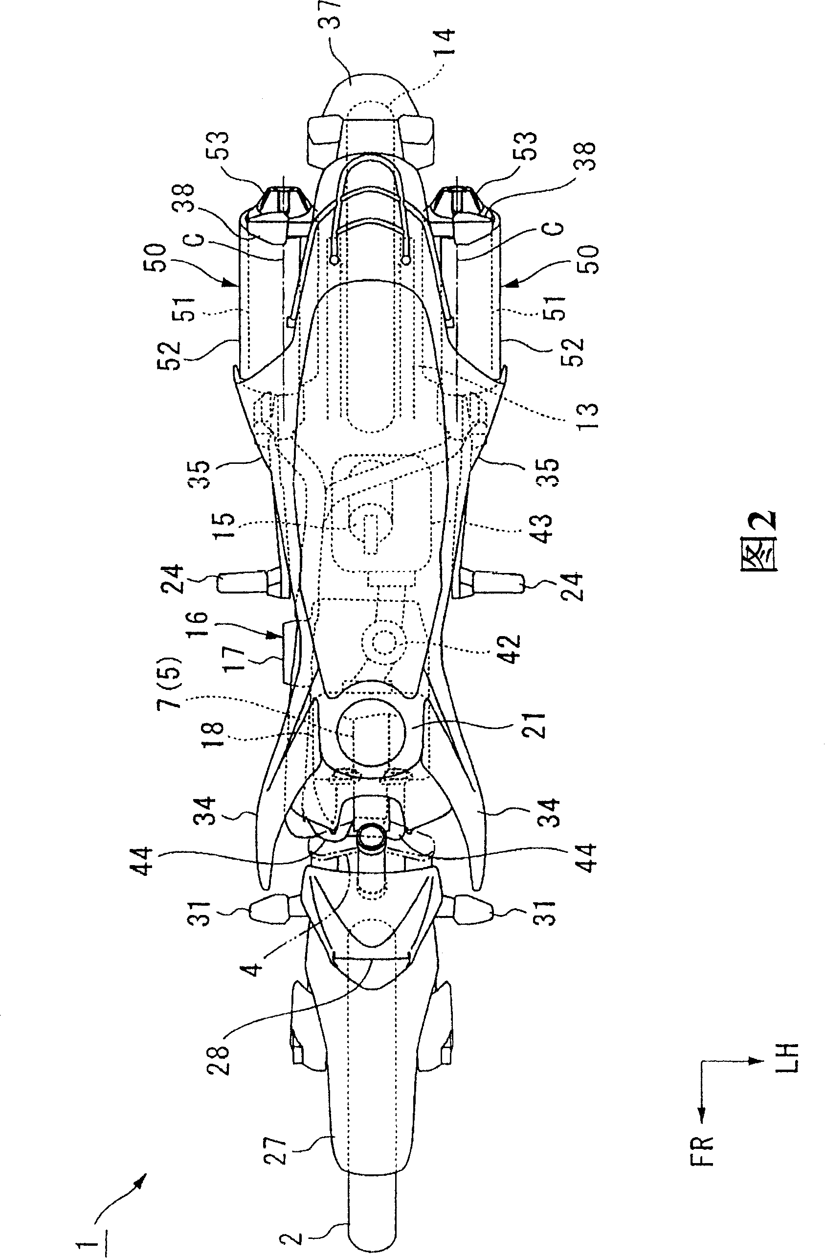
[0031] Embodiments of the present invention will be described below with reference to the drawings. Unless otherwise specified, directions such as front, rear, left, and right in the following description are the same as those in the vehicle. In the drawings, arrow FR indicates the front of the vehicle, arrow LH indicates the left side of the vehicle, and arrow UP indicates the upper side of the vehicle.

[0032] As shown in FIG. 1 , a pair of left and right front forks 3 pivotally supporting front wheels 2 of a motorcycle (vehicle) 1 are pivotally supported on a head pipe 6 of a vehicle frame 5 via a steering column 4 . The frame 5 is a cradle frame formed by joining the upper end of the upper tube 7 and the lower end of the down tube 8 near the rocker pivot 9, wherein the upper tube 7 extends rearward from the upper part of the head tube 6. Then bent downward, the downpipe 8 extends downward from the lower part of the head pipe 6 and then bends backward.

[0033] The front...


PUM


Abstract

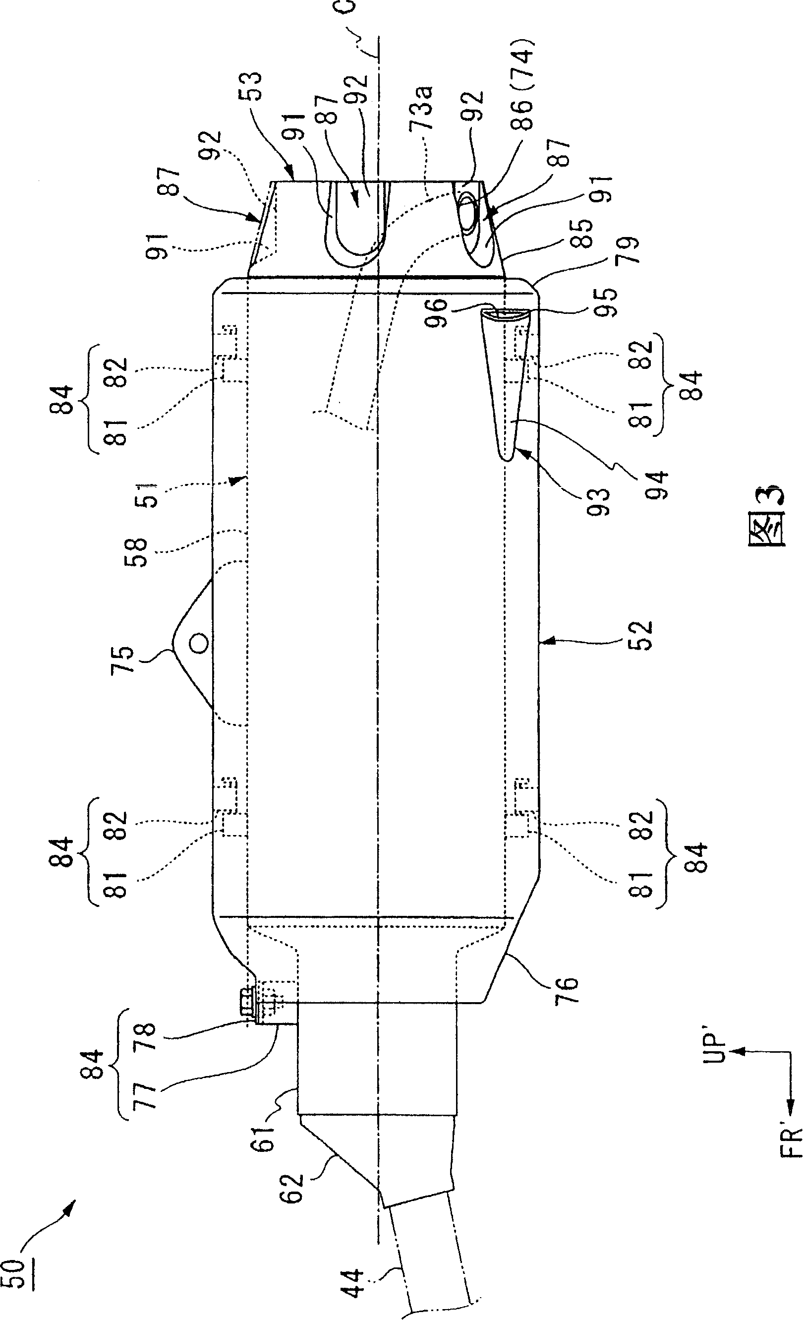
To provide a muffler device capable of improving discharge of exhaust gas, while discharging the exhaust gas in any desired direction. A muffler device 50 is provided. The muffler device 50 is connected to a rear end portion of an exhaust pipe 44 extending from an internal combustion engine of a vehicle. The following arrangements are made in this muffler device 50. Specifically, an exhaust outlet 74 opening outwardly and laterally the vehicle is disposed at a rear portion of a muffler main body 51. The muffler main body 51 is provided with a muffler side cover 52 and an end cap 53 as muffler covers. The muffler side cover 52 includes a slit 96. The slit 96 serves as an air intake guide shaped portion for guiding running wind so that the running wind crosses the exhaust outlet 74.

Description

technical field [0001] The present invention relates to a muffler device applied to vehicles such as motorcycles. Background technique [0002] Conventionally, a muffler device connected to the rear end of an exhaust pipe extending from a vehicle internal combustion engine bends an exhaust tail pipe forming an exhaust outlet in a desired direction (for example, outside the vehicle) (for example, refer to Patent Document 1). [0003] Patent Document 1: Japanese Patent Publication No. 5-38122 [0004] In recent years, attention has been paid to reducing the size and weight of the vehicle body and the reduction of exhaust noise. For this reason, when the muffler body is downsized and the noise reduction performance is improved, the use of the above structure will reduce the exhaust gas emission performance. Contents of the invention [0005] Therefore, the present invention provides a muffler device capable of discharging exhaust gas in a desired direction and improving exha...

Claims


Application Information

Patent Timeline
Patent Type & Authority Patents(China)
IPC IPC(8): F01N1/00F01N7/00B62M7/02F01N3/02F01N13/08F01P1/06
CPCF01N1/089F01N13/14F01N3/05F01N2310/02F01N13/082F01N1/084Y02T10/20Y02T10/12
Inventor 山口隆志坂田裕基石栗嘉之
Owner HONDA MOTOR CO LTD
Learn More