Varifocus lens device

A zoom lens and mirror chamber technology, which is applied in projection devices, printing devices, installations, etc., can solve the problems of tilting the lens, affecting the imaging quality, and uneven force on the spring 92, so as to reduce the size of the mechanism, ensure the image quality, and stretch smooth effect

Inactive Publication Date: 2008-06-11
ASIA OPTICAL CO INC
View PDF6 Cites 0 Cited by
  • Summary
  • Abstract
  • Description
  • Claims
  • Application Information

AI Technical Summary

Problems solved by technology

[0005] Above-mentioned optical zoom lens device, the axial positioning of its camera lens is realized by screw 91 and spring 92, because screw 91 is arranged on the position deviated from optical axis, turning screw 91 makes spring 92 everywhere be stressed unevenly easily, thereby makes lens Tilting occurs, which affects the imaging quality; secondly, the spring 92 must leave a certain stretchable space in the moving direction of the lens, so that the axial length of the optical zoom lens device is too large, and the overall mechanism size of the device is difficult to be effectively reduced; Moreover, the connection between the lens and the lens holder 90 is through the cooperation of the outer wall of the lens and the inner wall of the lens holder. Because it is a precision instrument, the smoothness of each matching plane is extremely high, and in the actual processing process, it is not easy to process an ideal surface. Therefore, it will affect the stability when the lens mount 90 drives the lens to move, and it will also affect the image quality

Method used


Image

  • Varifocus lens device
  • Varifocus lens device
  • Varifocus lens device

Examples


Embodiment Construction

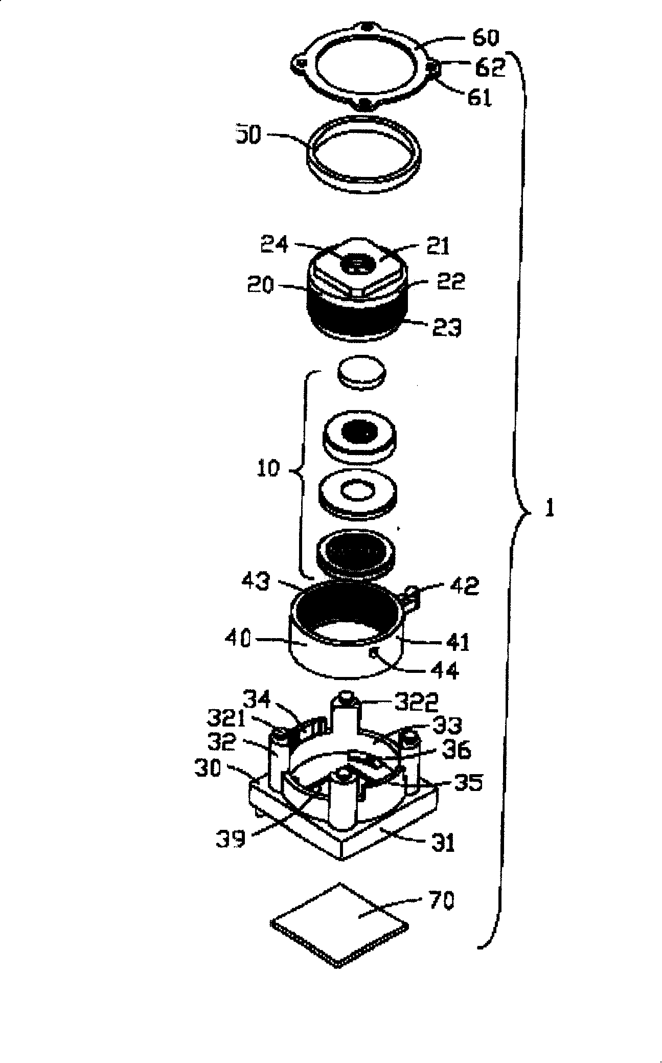
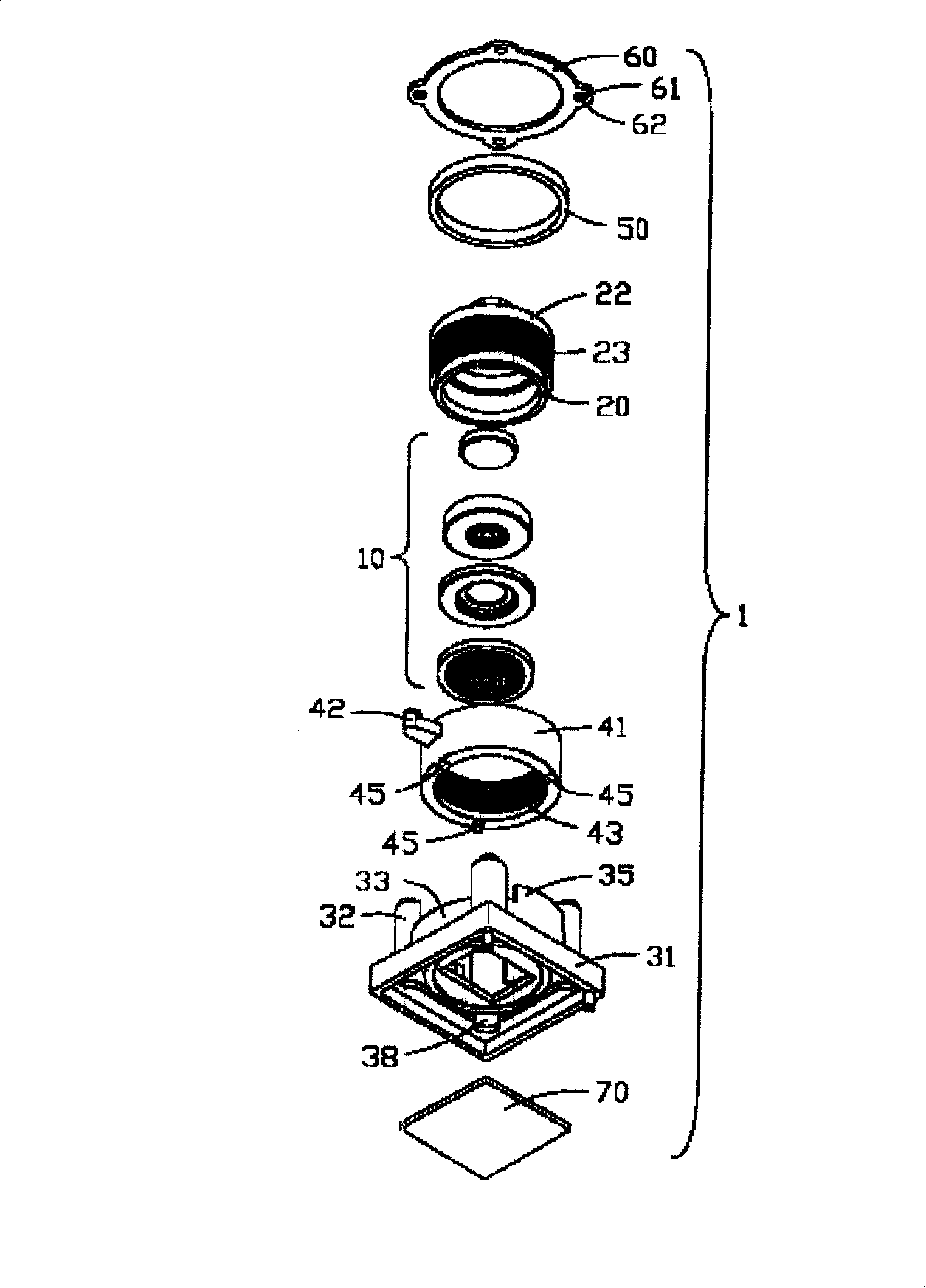
[0017] The zoom lens device 1 of the present invention is applied to mobile electronic devices such as digital cameras or mobile phones with digital camera lenses. Please refer to figure 2 and image 3 As shown, the zoom lens device 1 of the present invention mainly includes: a lens (not labeled), a socket 30 , a focus ring 40 , an elastic washer 50 and a cover 60 . The lens includes an optical lens group 10 composed of several optical lenses and a mirror chamber 20 for accommodating the optical lens group 10 . The zoom lens device 1 also includes an image sensing component 70 for imaging, such as a charge-coupled device (Charge-Coupled Device, CCD) or a complementary metal oxide semiconductor (Complimentary Metal Oxide Semiconductor, CMOS).

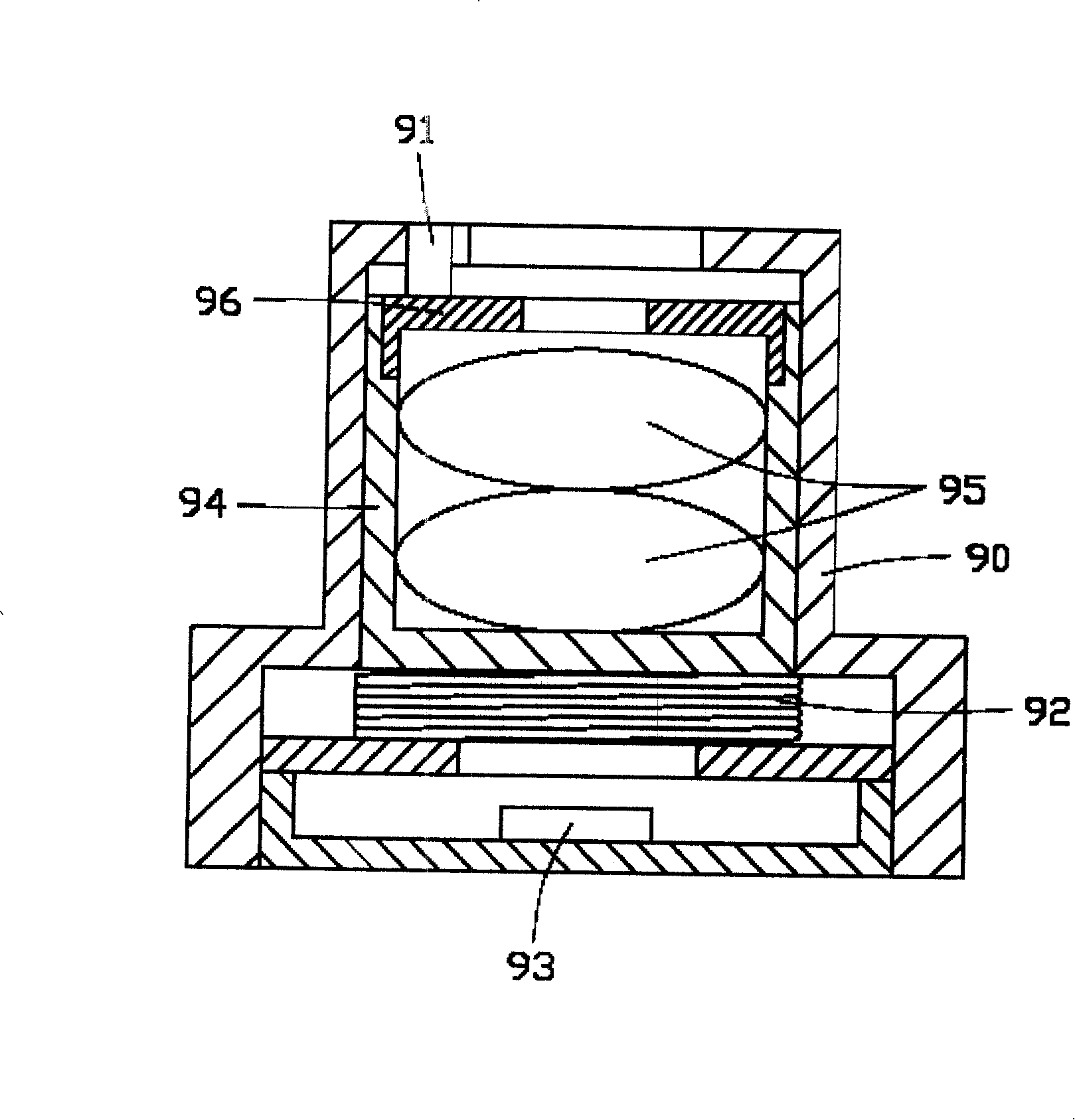
[0018] The mirror chamber 20 includes a substantially stepped lens housing portion 22 for housing a plurality of optical lenses with different thicknesses and radii, and a boss 21 with a light hole 24 in the center for light to pass t...


PUM


Abstract

The invention provides a focal variation lens device including the bearing seat, the rotated focusing ring connected to the bearing seat, the lens room located in the focusing ring, the elastic gasket and the cover. The matched displacement guide rail and the sliding part are set between the focusing ring and the bearing seat. The sliding part can move along with the displacement guide rail to drive the focusing ring move comparing to the bearing seat. At the same time, lens room can move with the focusing ring and generates the axis displacement relative to the bearing seat. The cover is matched to the bearing seat and the elastic gasket is clapped between the cover and the focusing ring. The lens of the invention has the small size and is easy to operate, so the lens has the good imaging quality.

Description

【Technical field】 [0001] The invention relates to a zoom lens device, in particular to a zoom lens device which is suitable for a mobile phone and a digital camera capable of taking pictures in a normal state and capable of taking close-up shots. 【Background technique】 [0002] With the development of multimedia technology, while people are pursuing thinner and smaller personal digital consumer products, they also put forward more requirements for their practical functions. Taking mobile phones as an example, the simple call function can no longer meet people's needs. More and more mobile phone manufacturers have begun to study new mobile phones that integrate digital camera camera functions, that is, adding lenses and corresponding circuit control systems inside the mobile phone, so as to realize mobile phones. The function of taking pictures. Early mobile phones with camera functions were all equipped with fixed-focus lenses, and their shooting range, especially close-up ...

Claims


Application Information

Patent Timeline
Patent Type & Authority Patents(China)
IPC IPC(8): G02B7/04G02B15/14G03B5/00G03B30/00
Inventor 赖建男
Owner ASIA OPTICAL CO INC
Why Eureka
Try Eureka