Efficient and self-locking electronic mechanical brake

An electro-mechanical braking and self-locking technology, applied in the type of brake, the brake on the axial direction, the components of the brake, etc., can solve the problem of not meeting the requirements of smooth transmission, low noise, inability to automatically adjust the braking gap, and high requirements for motor braking. Advanced problems, to achieve the effect of ingenious structural design, low noise and high coincidence

Pending Publication Date: 2021-09-24
HEFEI UNIV OF TECH
View PDF0 Cites 0 Cited by
  • Summary
  • Abstract
  • Description
  • Claims
  • Application Information

AI Technical Summary

Problems solved by technology

[0003] However, the existing EMB also finds some shortcomings: 1. The existing electromechanical brake does not have a self-locking structure, and there will be a problem of motor stalling for a long time when braking on a long slope, which will shorten the service life of the motor
2. None of the existing EMB brakes can automatically adjust the brake clearance
3. The requirement for motor braking force is relatively high. If a larger transmission ratio is not used, the size of the motor will be larger and it will not be possible to find a suitable installation space
4. The existing EMB brake cannot meet the requirements of stable transmission and low noise during braking

Method used


Image

  • Efficient and self-locking electronic mechanical brake
  • Efficient and self-locking electronic mechanical brake
  • Efficient and self-locking electronic mechanical brake

Examples


Embodiment Construction

[0027] The following is a detailed description of the embodiments of the present invention. This embodiment is implemented on the premise of the technical solution of the present invention, and detailed implementation methods and specific operating procedures are provided, but the protection scope of the present invention is not limited to the following implementation example.

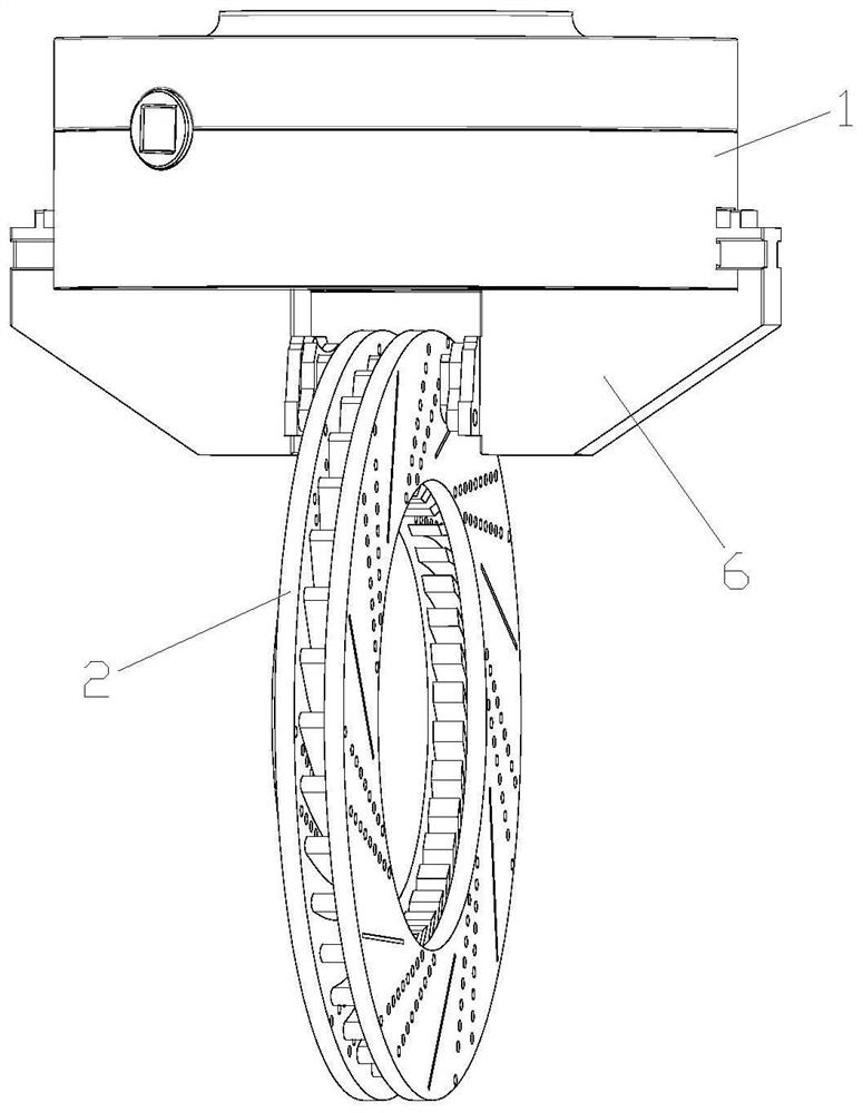
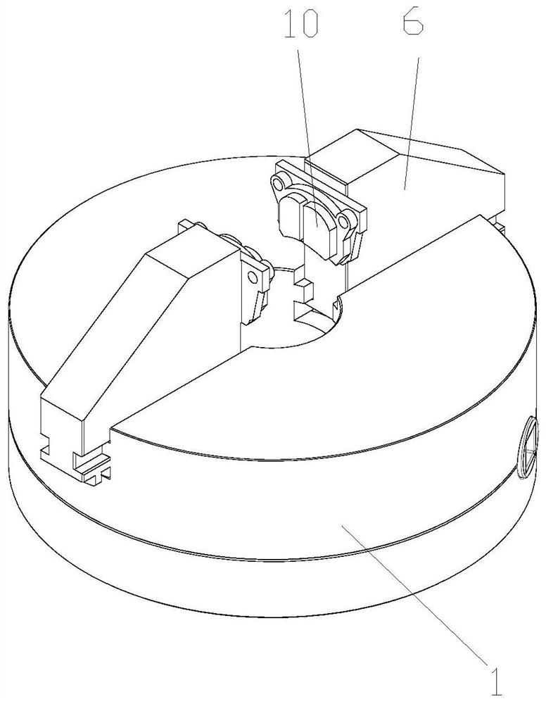
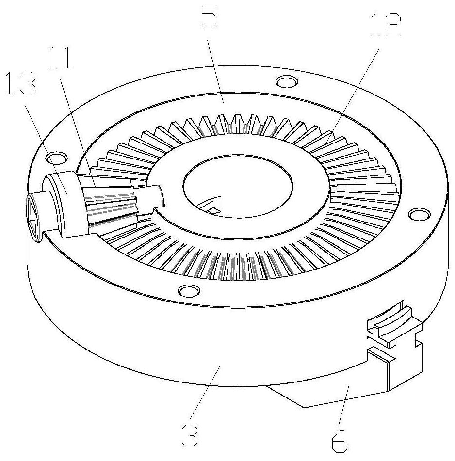
[0028] see Figure 1 to Figure 7 , this embodiment discloses a high-efficiency, self-locking electromechanical brake, including a brake box 1 fixedly connected to the frame, a brake disc 2 fixedly connected to the wheel, the brake box 1 is composed of a brake box body 3 and a The brake case 3 is fixedly connected with the brake case cover 4, and the brake case 3 and the brake case cover 4 jointly form an annular installation cavity 5. Two left and right brake calipers 6 are arranged on the bottom of the brake box 1 , and the brake calipers 6 can only slide back and forth along the left and right direc...


PUM


Abstract

The invention discloses an efficient and self-locking electronic mechanical brake. The efficient and self-locking electronic mechanical brake comprises a brake box and a brake disc, two brake calipers are arranged at the bottom of the brake box, the brake disc is located between the two brake calipers, a transmission mechanism is arranged in an installation cavity in the brake box, and the two brake calipers are driven by the transmission mechanism to get close to each other or get away from each other, so that two friction plates are in contact with or are separated from the brake disc; and the transmission mechanism comprises a driving bevel gear and a driven bevel gear which are meshed with each other, equidistant spiral line tracks protruding downwards are arranged on the bottom wall face of the driven bevel gear, a plurality of equidistant arc-shaped sliding grooves matched with the equidistant spiral line tracks are formed in the top of each brake caliper, the driving bevel gear is driven by a motor to rotate, and under the cooperation of the equidistant spiral line tracks and the arc-shaped sliding grooves, the rotating driven bevel gear drives the two brake calipers to move reversely in the left-right direction. The efficient and self-locking electronic mechanical brake has the advantage of realizing efficient, stable, soft, continuous and adjustable braking force output.

Description

technical field [0001] The invention relates to a wire-controlled brake for vehicles, in particular to a high-efficiency, self-locking electromechanical brake. Background technique [0002] With the development of automobile intelligence, the chassis system by wire is the development trend of the automobile industry at this stage. As an important part of smart cars, the brake-by-wire system is directly related to driving safety issues. Enterprises and scholars related to automobile brakes at home and abroad have proposed innovative structures for brake-by-wire. At present, the brake-by-wire mainly includes two types: Electro-hydraulic Brake (EHB for short) and Electro-Mechanical Brake (EMB for short). Among them, EMB directly cancels the brake master cylinder and hydraulic pipeline, integrates the motor on the brake caliper, and the brake signal generated by the pedal is directly input to the brake motor, which simplifies the intermediate process from signal input to brake...

Claims


Application Information

Patent Timeline
Patent Type & Authority Applications(China)
IPC IPC(8): F16D55/226F16D65/853F16D121/24
CPCF16D55/226F16D65/853F16D2121/24
Inventor 续宁魏书枚李维汉白先旭
Owner HEFEI UNIV OF TECH
Why Eureka
Try Eureka