
Light conducting plate and manufacturing method thereof

A manufacturing method and technology for a light guide plate, which are applied in optics, nonlinear optics, instruments, etc., can solve the problems of low light uniformity of the light guide plate, and achieve the effects of improving light utilization rate, uniform brightness, and simple production.

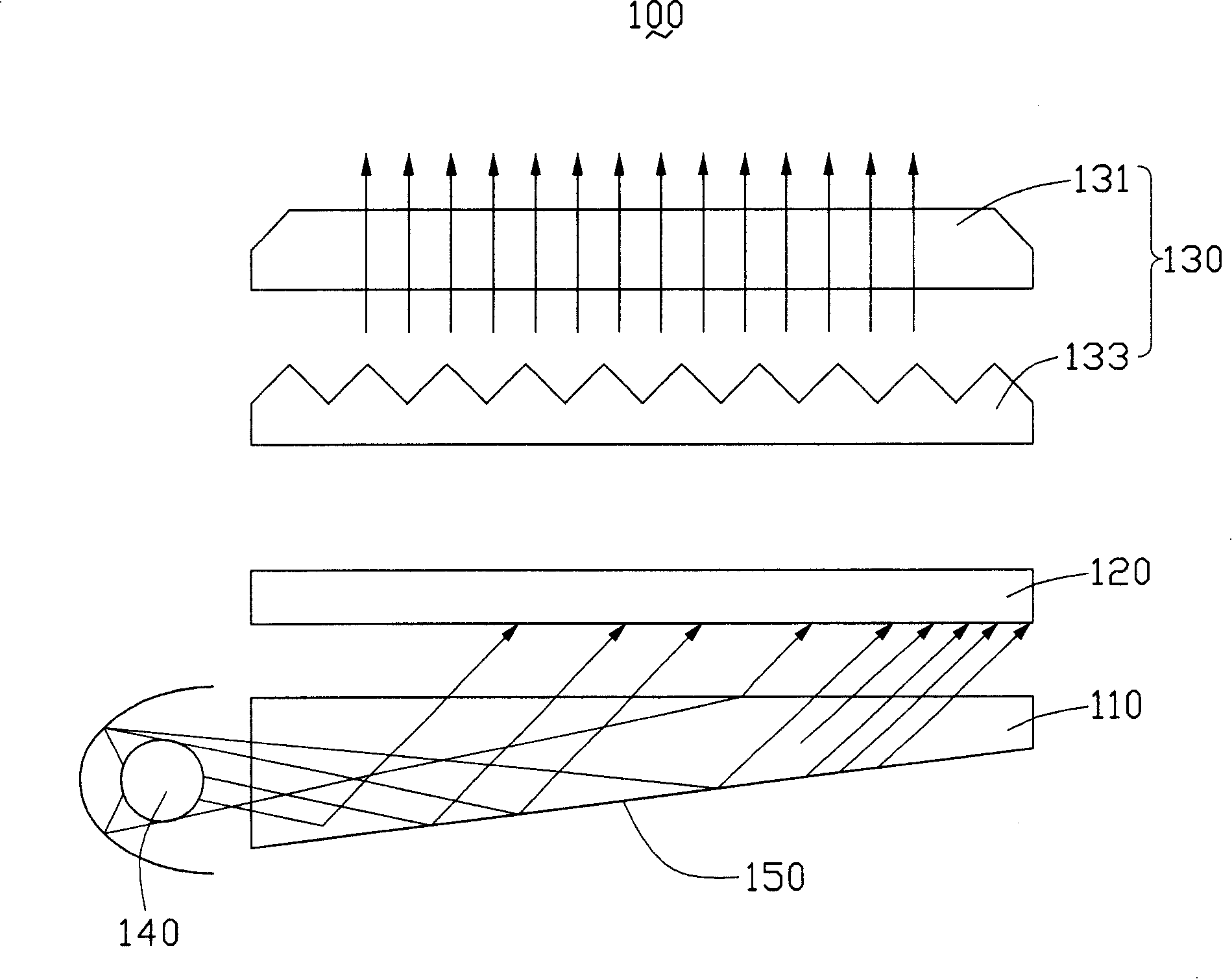
Inactive Publication Date: 2008-06-18
HONG FU JIN PRECISION IND (SHENZHEN) CO LTD +1
View PDF5 Cites 0 Cited by
  • Summary
  • Abstract
  • Description
  • Claims
  • Application Information

AI Technical Summary

Problems solved by technology

[0007] In order to overcome the defect of low light uniformity of the light guide plate in the prior art, the present invention provides a light guide plate with high light uniformity

Method used


Image

  • Light conducting plate and manufacturing method thereof
  • Light conducting plate and manufacturing method thereof
  • Light conducting plate and manufacturing method thereof

Examples


Embodiment Construction

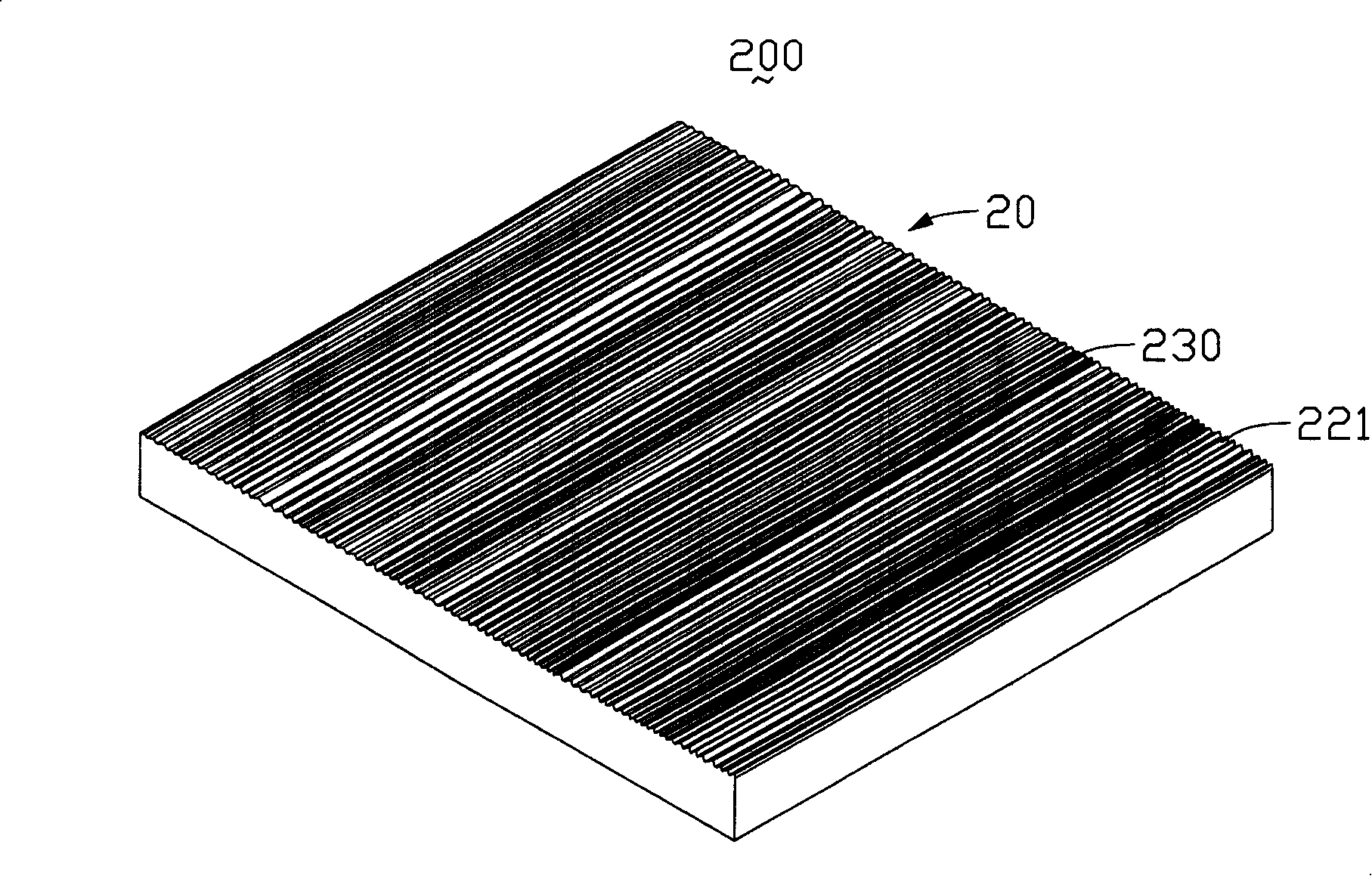
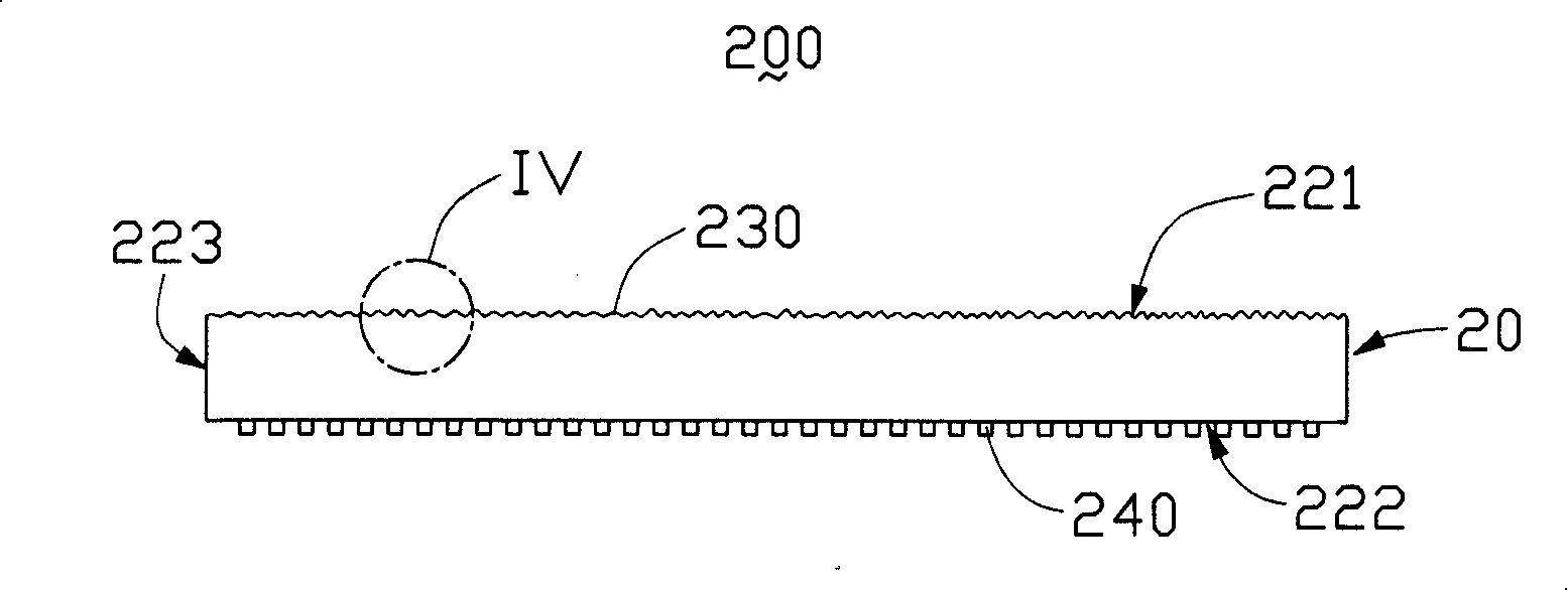
[0018] see figure 2 , image 3 The light guide plate 200 of the present invention includes a light-transmitting plate 20 , and the light-transmitting plate 20 includes a light incident surface 223 , a light exit surface 221 perpendicular to the light incident surface 223 , and a bottom surface 222 opposite to the light exit surface 221 . The light guide plate 200 of the present invention also includes a plurality of scattering points 240 . The plurality of scattering points 240 are evenly distributed on the bottom surface 222 of the light-transmitting plate 20 , and the material used is a high-scattering light substance, and its shape can be columnar, spherical or tetrahedral. The plurality of scattering points 240 can scatter and reflect the incident light beam from the side, destroying the total reflection condition of the light beam inside the transparent plate 20 , and make the light beam uniformly output from the light emitting surface 221 of the light transparent plate...


PUM


Abstract

This invention discloses a light conduction plate and its manufacturing method, among which, said plate includes a transmission plate containing an entering face and an outgoing face for outgoing beams and a bottom corresponding to it, in which, the outgoing face is distributed with silk-like projectors. The method includes the following steps: processing a parent mode forming a core in it, processing a draw structure on the core by a mechanical grinder, manufacturing light conduction plate by an emit formation method.

Description

【Technical field】 [0001] The invention relates to a light guide plate and a manufacturing method thereof. 【Background technique】 [0002] Since the liquid crystal in the LCD panel itself does not have light-emitting characteristics, in order to achieve the display effect, it is necessary to provide the LCD panel with a light source device, such as a backlight module, whose function is to supply the LCD panel with a surface with sufficient luminance and uniform distribution. light source. [0003] The prior art backlight module is composed of a light source, a reflector, a light guide plate, a diffuser plate and a prism layer, etc., wherein the light guide plate is a key component in the backlight module, and its function is to guide the incident light to be converted into surface light source. In order to make the luminance distribution of the surface light source more uniform, a diffuser plate is usually arranged on one side of the light-emitting surface of the light guid...

Claims


Application Information

Patent Timeline
Patent Type & Authority Patents(China)
IPC IPC(8): G02F1/1335G02F1/13357
Inventor 余泰成吕昌岳陈杰良
Owner HONG FU JIN PRECISION IND (SHENZHEN) CO LTD
Learn More