Traveling wave optical modulator and its regulating method

A technology of optical modulators and adjustment methods, which is applied in the fields of instruments, optics, nonlinear optics, etc., can solve problems such as complicated operations, deterioration of jitter, matching problems between drive drivers and optical modulators, etc., to expand the freedom of combination and expand the combination The effect of degrees of freedom

Active Publication Date: 2008-07-09
SUMITOMO OSAKA CEMENT CO LTD
View PDF4 Cites 0 Cited by
  • Summary
  • Abstract
  • Description
  • Claims
  • Application Information

AI Technical Summary

Problems solved by technology

[0015] In addition, although the frequency characteristics of the driving driver and the optical modulator are good individually, when the two are combined, there are many cases where the jitter deteriorates, and the matching of the driving driver and the optical modulator is also a problem.
[0016] Theref

Method used


Image

  • Traveling wave optical modulator and its regulating method
  • Traveling wave optical modulator and its regulating method
  • Traveling wave optical modulator and its regulating method

Examples


Embodiment Construction

[0054] Hereinafter, the present invention will be described in detail using preferred embodiments.

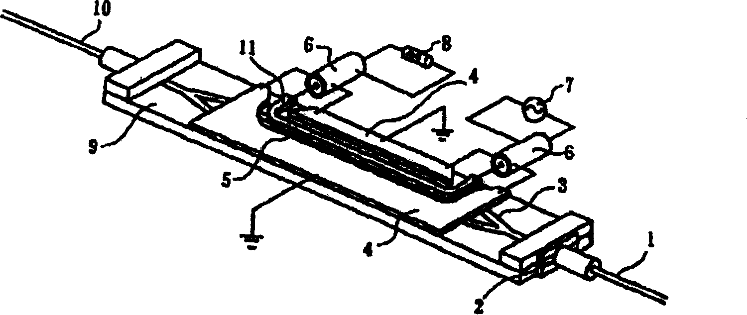
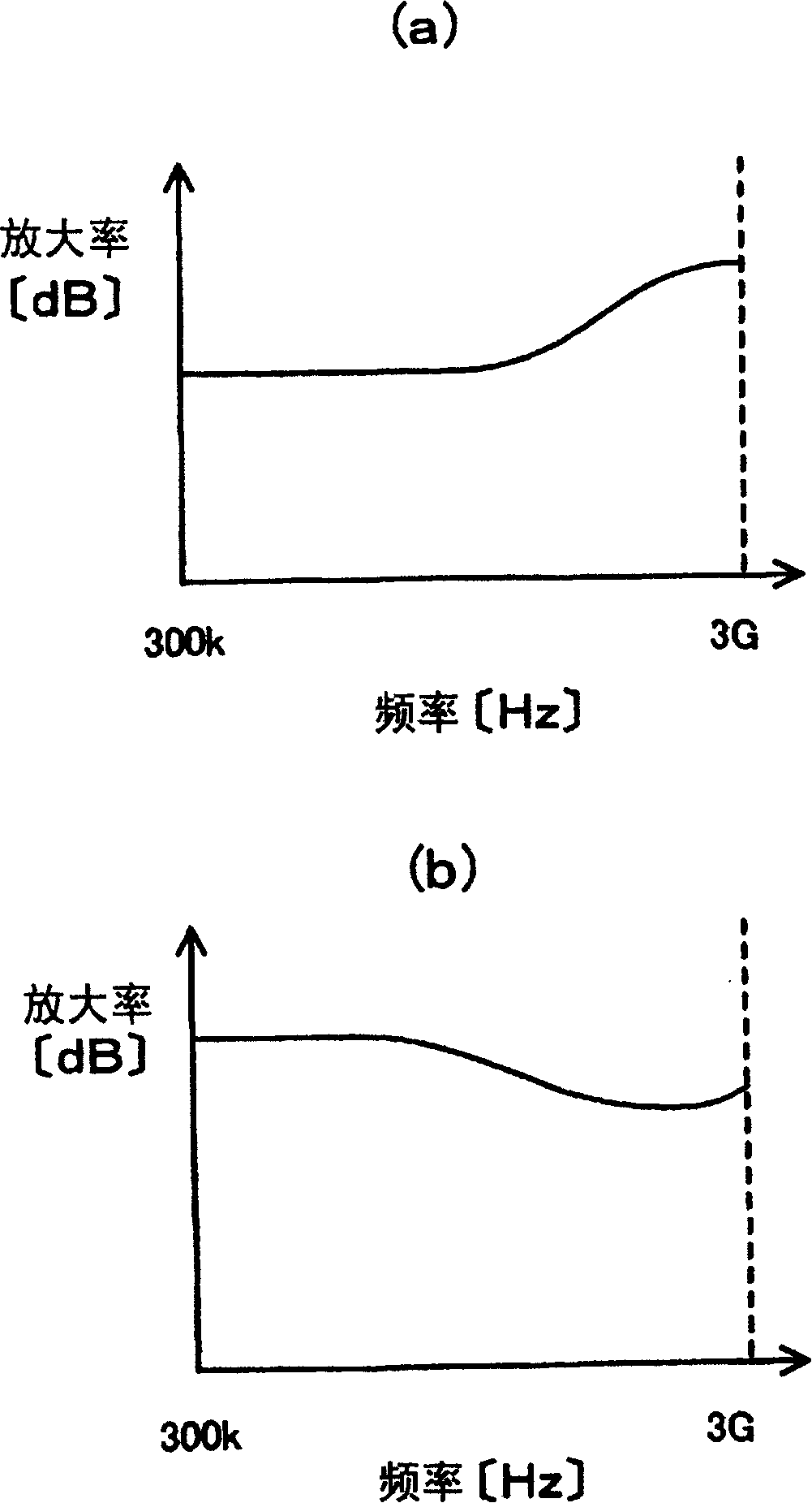
[0055] The present invention relates to a traveling-wave optical modulator and its adjustment method. The traveling-wave optical modulator comprises: a substrate with an electro-optical effect; an optical waveguide formed on the substrate; The electrode for modulation of light waves is characterized in that: a driving driver for driving and controlling the traveling wave optical modulator is connected to the above traveling wave optical modulator, in order to correct the frequency characteristic of the gain of the driving driver, the traveling wave optical modulator is adjusted. Frequency characteristics of the electrical / optical conversion response of an optical modulator.

[0056] In addition, the present invention relates to a traveling-wave optical modulator and its adjustment method. The traveling-wave optical modulator includes: a substrate with an electro-optical effect;...


PUM


Abstract

A traveling wave optical modulator in which occurrence of jitter is suppressed when it is driven through a driver, and its regulating method; especially in which the degree of freedom is enlarged in the combination of the driver and the traveling wave optical modulator and jitter can be suppressed effectively even after they are combined, and its regulating method. The traveling wave optical modulator comprises a substrate exhibiting electrooptic effect, an optical waveguide formed on the substrate, and a modulation electrode performing modulation control on a light wave propagating through the optical waveguide, characterized in that the traveling wave optical modulator is connected with a driver performing drive control thereof, and the frequency characteristics (b) of electrooptic conversion response of the traveling wave optical modulator is regulated to correct the frequency characteristics (a) of gain of the driver. Preferably, regulation of the frequency characteristics of electrooptic conversion response is characterized by the regulation of at least one of the impedance of the modulation electrode or the impedance of a termination resistor.

Description

technical field [0001] The present invention relates to a traveling-wave optical modulator and its adjustment method, in particular to a traveling-wave optical modulator for driving and controlling a driving driver connected to the traveling-wave optical modulator. device and its adjustment method. Background technique [0002] In recent years, when evaluating optical modulators, attention has been drawn to the characteristic called jitter, which shows how the optical signal obtained when the optical modulator is driven vibrates over time. [0003] Jitter is an indicator that indicates the vibration of an optical signal over time, such as figure 1 As shown in , the optical eye pattern waveform is accumulated and defined as the amplitude at signal crossover. [0004] In order to improve the jitter of the optical signal obtained when the optical modulator is driven, it is necessary to improve the following characteristics for the optical modulator or the driver for driving a...

Claims


Application Information

Patent Timeline
IPC IPC(8): G02F1/03G02F1/035
Inventor 清水亮丸山大志菅又彻
Owner SUMITOMO OSAKA CEMENT CO LTD
Why Eureka
Try Eureka