Electromagnetic clutch

An electromagnetic clutch and drive shaft technology, applied in clutches, magnetic drive clutches, non-mechanical drive clutches, etc., can solve the problems of shortened response time, variation of torque release time, misalignment of rotation start time, etc., to achieve torque transmission time and torque The effect of shortening the release time, eliminating the deviation of the torque transmission time and torque release time, and improving the responsiveness

Active Publication Date: 2008-07-16
MITSUBISHI ELECTRIC CORP +1
View PDF5 Cites 0 Cited by
  • Summary
  • Abstract
  • Description
  • Claims
  • Application Information

AI Technical Summary

Problems solved by technology

[0014] However, in the conventional electromagnetic clutch, even after the coil 7 is demagnetized, the magnetic flux remains in the magnetic path forming members of the rotor 3, the armature 5, and the yoke 4, and there is a possibility that a residual attractive force is generated between the rotor 3 and the armature 5 and torque is transmitted. The armature 5 is thus forcibly pulled away from the rotor 3 by means of the return spring 6
[0015] However, when the return spring 6 is used, the time required for the rotor 3 and the armature 5 to be reliably connected when the coil 7 is excited due to the deviation of its elastic force (hereinafter referred to as the torque transmission time) and the demagnetization of the coil 7 are both 3, The time required for the combination of 5 to be released (hereinafter referred to as the torque release time) will vary.
[0016] Taking the above-mentioned image forming apparatus as an example, when the torque transmission time fluctuates, the rotation start timing of the counting drum deviates, causing the front end of the toner image formed on the photoreceptor drum to be misaligned with the front end of the sheet.
And when the torque release time changes, there will be problems such as the counting roller cannot stop at the normal position, and the sheet sent from the rear cannot be stopped.
[0017] In this way, as long as the return spring 6 is used, there will be deviations in the torque transmission time and torque release time due to the deviation of its elastic force. At the same time, the armature 5 needs to overcome the elastic force of the return spring 6 and combine with the rotor 3, so it is necessary to shorten the response time. There are limitations

Method used


Image

  • Electromagnetic clutch
  • Electromagnetic clutch
  • Electromagnetic clutch

Examples


Embodiment Construction

[0031] [Embodiment 1]

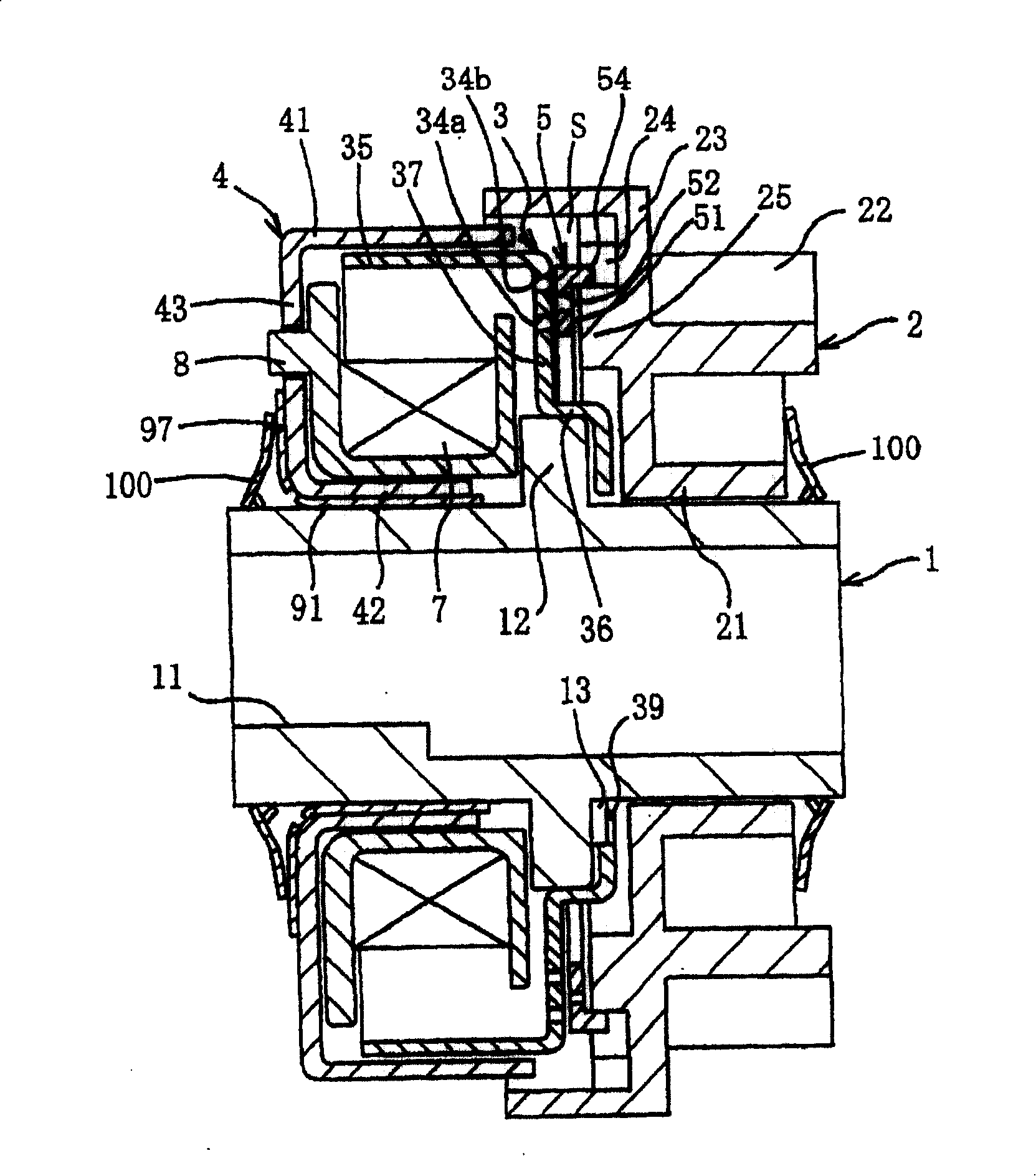
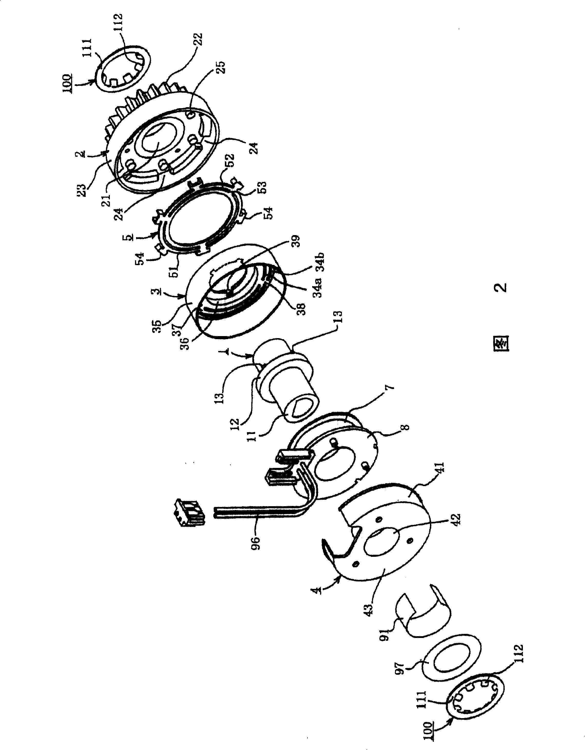
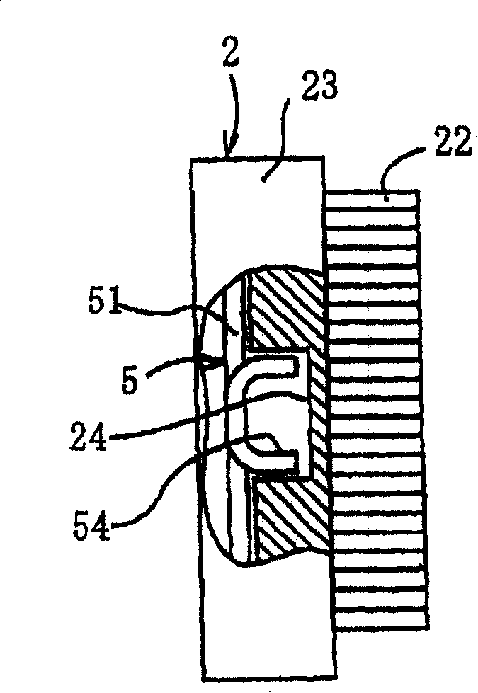
[0032] figure 1 It is a side sectional view showing the electromagnetic clutch according to Embodiment 1 of the present invention, and FIG. 2 is an exploded perspective view showing the same electromagnetic clutch, image 3 It is a partially cutaway side view showing the assembled state of the armature and the rotating body. FIG. 4 shows the shape of the retaining ring. The same figure (a) is its front view, and the same figure (b) is its side view. right with Figure 9 The corresponding components of the shown conventional technology are marked with the same symbols.

[0033] The electromagnetic clutch according to Embodiment 1 is mainly composed of a drive shaft 1, a rotating body 2, a rotor 3, a yoke 4, an armature 5, and a coil 7, and a conventional return spring is omitted.

[0034] The drive shaft 1 is hollow, and its D-cut portion 11 having a D-shaped cross section is connected to a load not shown (in the case of an image forming apparatus, th...


PUM


Abstract

To provide an electromagnetic clutch capable of dispensing with a conventional return spring and shortening both of torque transmission time and torque release time between a rotor and an armature and having excellent response property. A magnetic path forming member including the rotor 3, the armature 5, and a yoke 4 is a soft magnetic body. The armature 5 is arranged slidably along the axial direction in an internal space S surrounded by the rotor 3 and a rotary body 2. Engaging pieces 54 protruding toward the rotary body 2 are formed in a plurality of sections along the peripheral direction of the armature 5. Armature locking parts 24 engaging with the engaging pieces 54 are formed in the rotary body 2.

Description

technical field [0001] The present invention relates to a small electromagnetic clutch. Background technique [0002] For example, in image forming apparatuses such as copiers and printers, in order to make the front end of the toner image formed on the photoreceptor drum coincide with the paper feeding time of the front end of the paper, by combining The electromagnetic clutch is connected to drive the counting roller to transfer the image on the proper position of the paper. [0003] As a small electromagnetic clutch suitable for such an image forming apparatus, there have been conventionally provided, for example, Figure 9 The structure shown (for example, refer patent document 1 etc.). [0004] This electromagnetic clutch has a hollow drive shaft 1, and a D-cut portion 11 of the drive shaft 1 having a D-shaped cross section is connected to a load not shown (in the case of the image forming apparatus described above, the shaft of the counter roller). The rotating body ...

Claims


Application Information

Patent Timeline
Patent Type & Authority Patents(China)
IPC IPC(8): F16D27/10
Inventor 酒本宪尔宫元美良
Owner MITSUBISHI ELECTRIC CORP
Why Eureka
Try Eureka