
DC power coverting circuit and DC power coverting device

A technology of DC power supply and conversion circuit, applied in the direction of conversion equipment without intermediate conversion to AC, can solve the problems of increased cost of clock generators and flexible printed circuit boards, circuit charge attenuation, conversion efficiency limitations, etc., to reduce electromagnetic The effect of interference, reducing the number of cables, and improving the driving ability

Inactive Publication Date: 2008-07-23
TPO DISPLAY
View PDF2 Cites 0 Cited by
  • Summary
  • Abstract
  • Description
  • Claims
  • Application Information

AI Technical Summary

Problems solved by technology

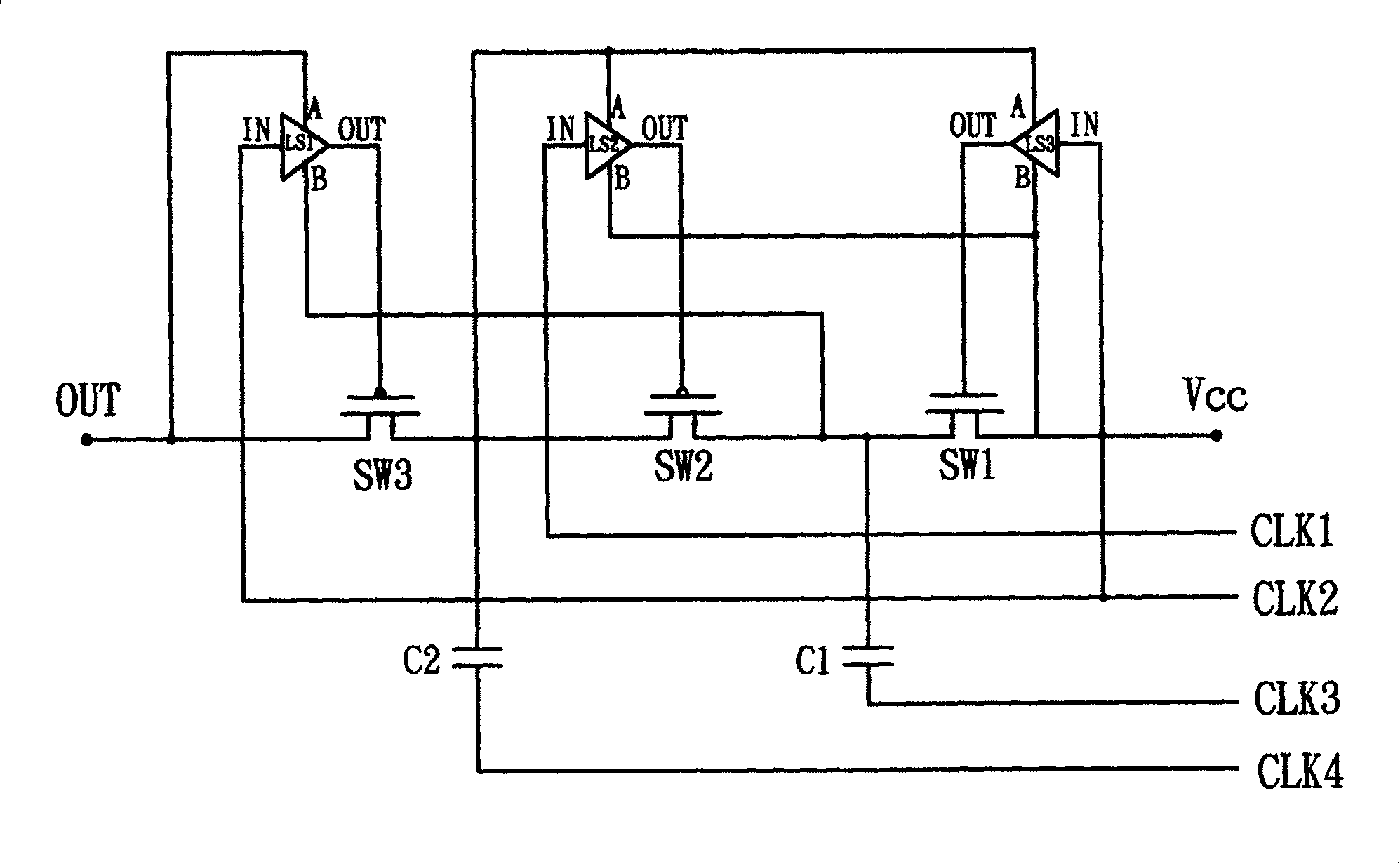
[0004] However, the above-mentioned DC step-up and step-down circuits use the shift circuits LS1, LS2, LS3 to control the switches SW1, SW2, SW3, because the shift circuits LS1, LS2, LS3 will have a phase delay phenomenon, so in order to ensure the phase In order to achieve the expected conversion efficiency, at least three sets of clocks are required to operate when the primary voltage is to be adjusted (boost or buck), and when the secondary voltage is to be adjusted (boost or buck), it must be Four sets of clocks can operate, so the required clock generators must also be set in multiple sets, and the clock signals generated by these clock generators are generally used on the display by a flexible printed circuit board (Flexible Print Circuit, FPC) It is connected to the boost and step-down circuits, so the number of wiring on the flexible printed circuit board must also increase accordingly, and the increase in the number of wiring on the clock generator and the flexible printed circuit board will inevitably increase the cost of manufacturing
[0005] In addition, when the shift circuits LS1, LS2, LS3 are used as the controllers of the switches SW1, SW2, SW3, the shift circuits LS1, LS2, LS3 are generally composed of a plurality of transistors, so higher power consumption will be generated , so it will instead cause the charge decay of the overall circuit and limit the conversion efficiency of the output

Method used


Image

  • DC power coverting circuit and DC power coverting device
  • DC power coverting circuit and DC power coverting device
  • DC power coverting circuit and DC power coverting device

Examples


Embodiment Construction

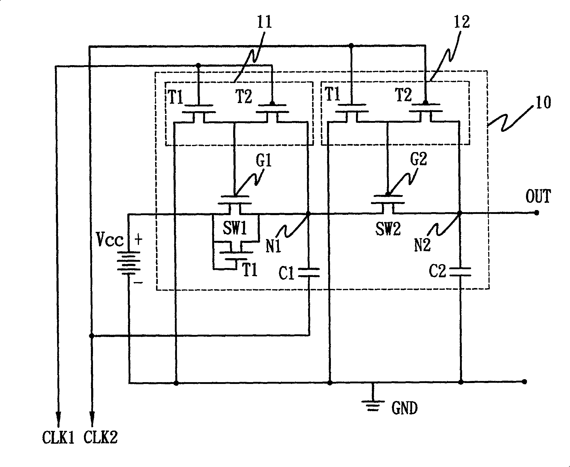
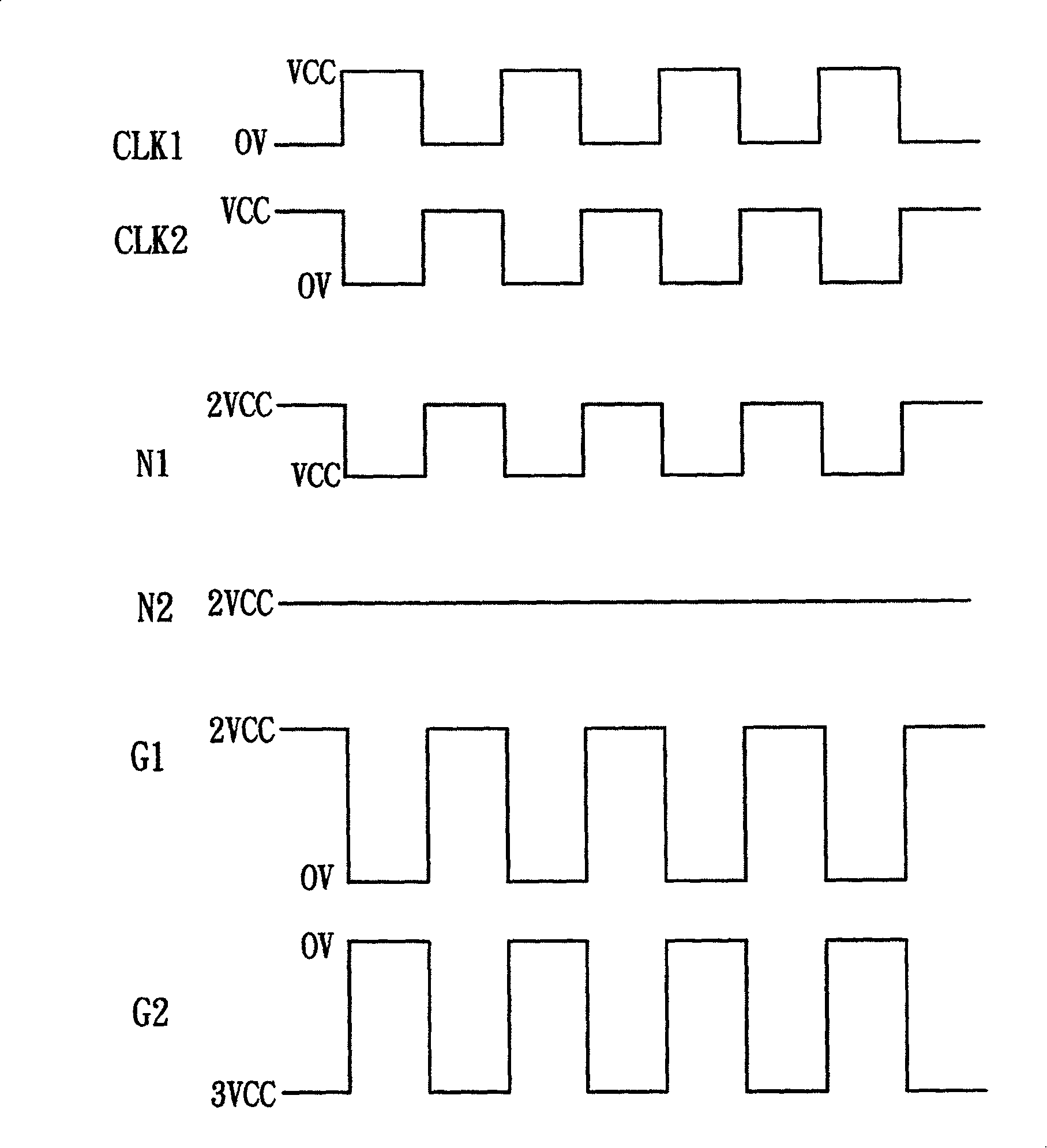
[0055] The DC power conversion circuit of the present invention is applied to a display circuit to generate a boost power, which can be divided into first-stage boost, second-stage boost...N-stage boost and so on. Each step of the boost can be achieved by a set of boost circuits, and each set of boost circuits consists of two sets of converters, two sets of switches, and a capacitor with boost function (one end of the capacitor is connected to a clock) , And then connect a capacitor with the function of storing voltage to the output terminal after boosting (one end of the capacitor is grounded). When you want to perform a second-stage boost, you can use a first-stage boost circuit as the basis. Each additional booster circuit can double the power supply Vcc). The following will be based on the first-stage boost and the second-stage boost. Illustrative.

[0056]

[0057] Such as figure 2 and image 3 Shown are an embodiment diagram of a DC power conversion circuit 10 with a first...


PUM


Abstract

The switching circuit of dc power supply includes following parts: a first converter is in use for inputting a first clock from its input end; a second converter is in use for inputting a second clock from its input end; the control end of first switch is connected to the output end of first converter, and the input end of first switch is in use for inputting a power source; the control end of second switch is connected to the output end of second converter, and the input end of second switch is in use for connecting to the output end of the first switch, and increased voltage being at the output end; one end of first capacitance is connected to the output end of first switch, and the other is in use for inputting the second clock; one end of the second capacitance is connected to the output end of second switch, and the other end is connected to a shared ground potential electrically. The invention generates an effect of voltage increase for dc power source.

Description

Technical field [0001] The present invention is a DC power conversion circuit used in an electronic device to generate power with different voltage potentials, and is particularly a boost type DC power conversion circuit controlled by a converter. Background technique [0002] With the development of the electronics industry, consumer electronics products have become more and more popular, especially after the development of the Internet and the widespread application of information technology, electronic information-related products have become mainstream products in the market, such as: thin film transistor liquid crystal displays, Organic light emitting diode displays, etc. Usually these electronic products need a variety of different voltage sources to provide different internal module circuits, such as: display scanning signal drive circuit, display data signal drive circuit, liquid crystal display backlight power supply or other control circuits, etc., its action The requir...

Claims


Application Information

Patent Timeline
Patent Type & Authority Patents(China)
IPC IPC(8): H02M3/06
Inventor 陈维成邱昌明林孝义
Owner TPO DISPLAY
Learn More