Resin-sealed semiconductor device and method of manufacturing the same
A resin sealing and semiconductor technology, applied in the fields of semiconductor/solid-state device manufacturing, semiconductor devices, semiconductor/solid-state device components, etc., can solve the problems of defective products and low yield of semiconductor device manufacturing.
- Summary
- Abstract
- Description
- Claims
- Application Information
AI Technical Summary
Problems solved by technology
Method used
Image
Examples
Embodiment 1
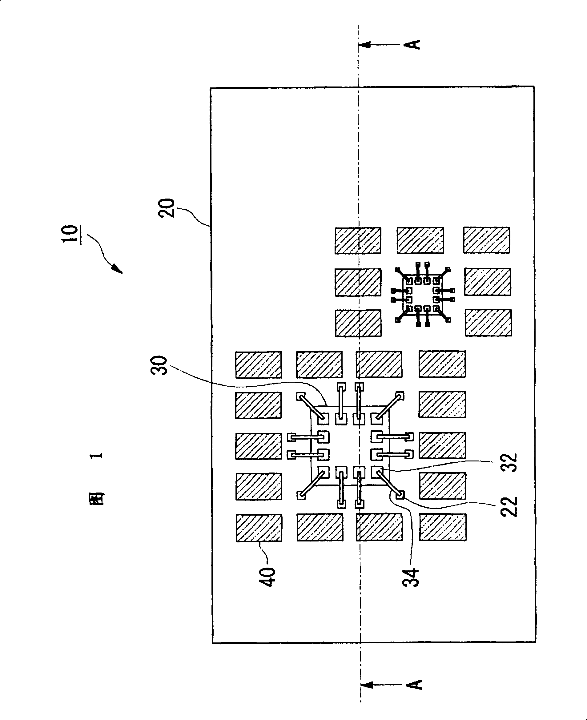
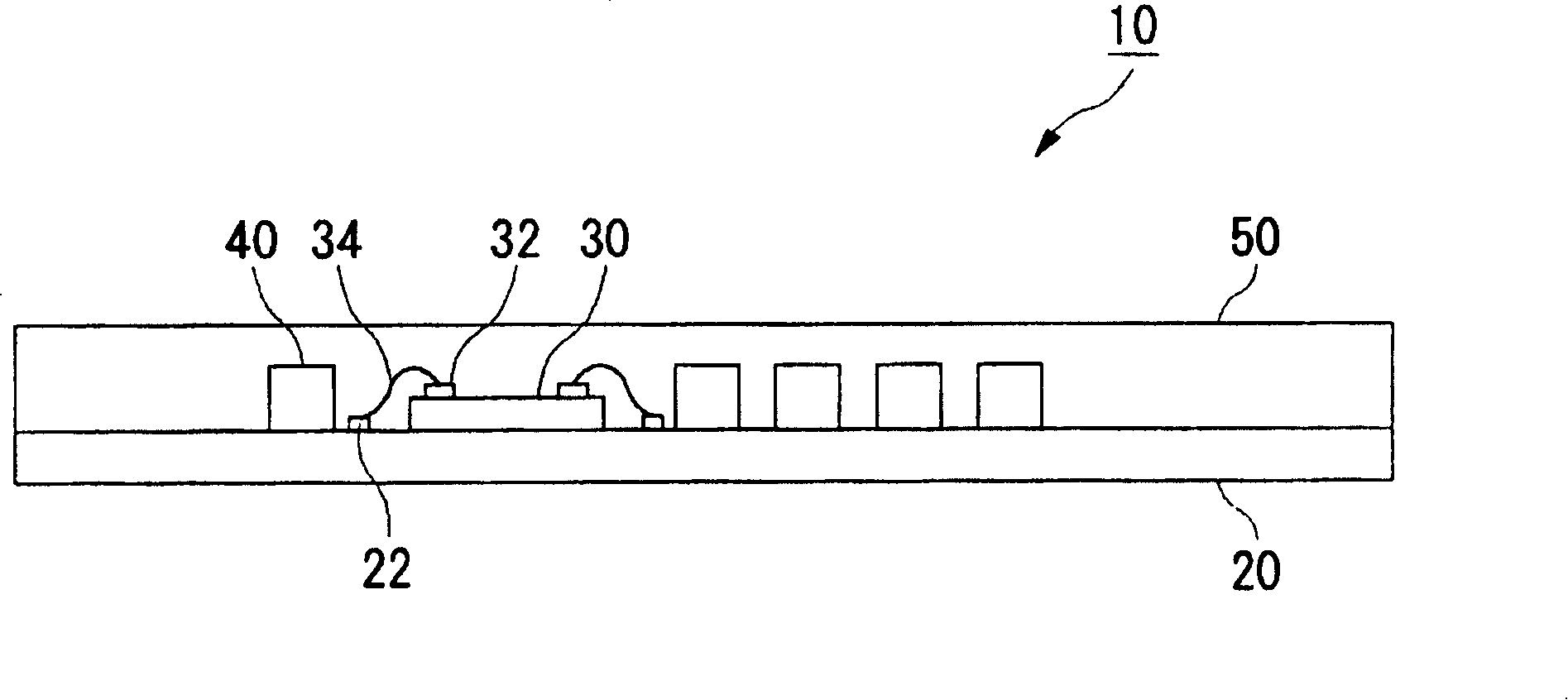
[0035] 1 is a plan view of a semiconductor device 10 of Embodiment 1, figure 2 It is a cross-sectional view taken along line A-A in FIG. 1 . The semiconductor device 10 has an insulating base member 20 , a semiconductor chip 30 , a plurality of sheet members 40 , and a molding resin 50 . The semiconductor chip 30 and the plurality of sheet members 40 are provided on the insulating base member 20 and sealed with a mold resin 50 molded by transfer film molding. In addition, the mold resin 50 is omitted from the plan view of FIG. 1 .
[0036] Materials constituting the insulating base member 20 include thermosetting materials such as melamine dielectrics such as BT resin, liquid crystal polymers, epoxy resins, PPE resins, polyimide resins, fluororesins, phenol resins, and polyamide bismaleimide. resin. The insulating base member 20 may be either a single layer or a multilayer.
[0037] The electrode pad 32 of the semiconductor chip 30 is electrically connected to the wire ele...
Embodiment 2
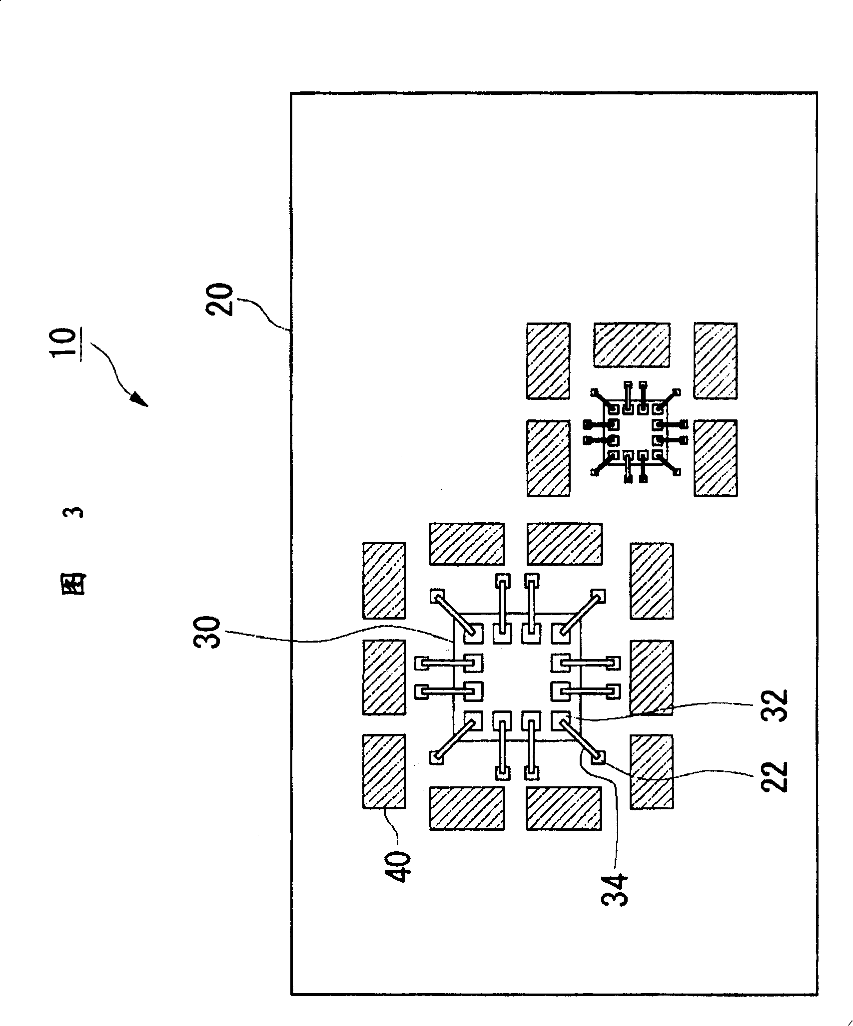
[0043] FIG. 3 is a plan view of the semiconductor device 10 of the second embodiment. The molding resin 50 is also omitted in FIG. 3 . In the semiconductor device 10 of the second embodiment, the longitudinal directions of the plurality of chip members 40 provided corresponding to the sides of the semiconductor chips 30 are along the sides of the semiconductor chips 30 . Therefore, when the molding resin 50 is injected by the transfer film molding method, even if the flow of the molding resin 50 is arranged toward either side of the semiconductor device 10 before molding, the sheet member 40 can effectively shield the flow of the semiconductor device 10 . Therefore, the flow of the molding resin 50 of the sheet 30 can be suppressed from the lead flow of the metal bonding wire 30 of the semiconductor device 10 , and the connection failure of the metal bonding wire 34 can be reduced.
Embodiment 3
[0045] FIG. 4 is a plan view of the semiconductor device 10 of the third embodiment. The molding resin 50 is also omitted in FIG. 4 . In the semiconductor device 10 of the third embodiment, the plurality of sheet members 40 are arranged along the peripheral portion of the insulating base member 20 . The longitudinal direction of each sheet member 40 faces a certain direction. Even with such a structure, when the molding resin 50 is injected by transfer film molding, the semiconductor device 10 before molding can be arranged so that the longitudinal direction of the sheet member 40 facing a certain direction is perpendicular to the direction of the molding resin 50. In this way, the sheet member 40 effectively blocks the flow of the molded resin 50 to the semiconductor chip 30, so that the wire flow of the metal bonding wire 30 of the semiconductor device 10 can be suppressed, and the connection failure of the metal bonding wire 34 can be reduced.
PUM
 Abstract
Description
Claims
Application Information
 - R&D
- Intellectual Property
- Life Sciences
- Materials
- Tech Scout
- Unparalleled Data Quality
- Higher Quality Content
- 60% Fewer Hallucinations
Browse by: Latest US Patents, China's latest patents, Technical Efficacy Thesaurus, Application Domain, Technology Topic, Popular Technical Reports.
© 2025 PatSnap. All rights reserved.Legal|Privacy policy|Modern Slavery Act Transparency Statement|Sitemap|About US| Contact US: help@patsnap.com


