Semiconductor parts and method for manufacturing integrate circuit chip
A technology of integrated circuits and semiconductors, applied in semiconductor/solid-state device manufacturing, semiconductor devices, semiconductor/solid-state device components, etc., to solve problems such as head breakage, impossibility to remove foreign particles, and reduced reliability of magnetic disk devices
- Summary
- Abstract
- Description
- Claims
- Application Information
AI Technical Summary
Problems solved by technology
Method used
Image

Examples
no. 1 example
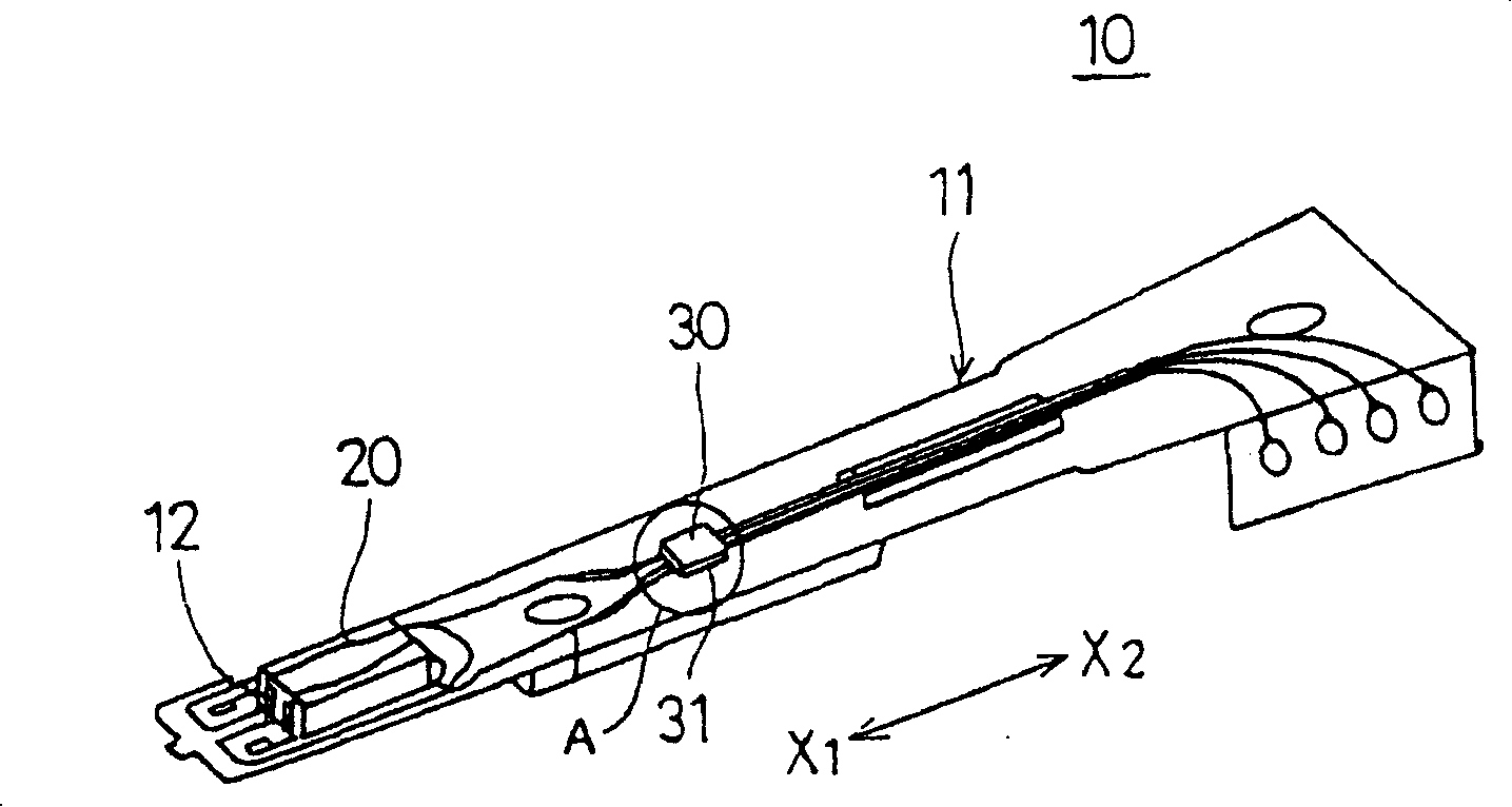
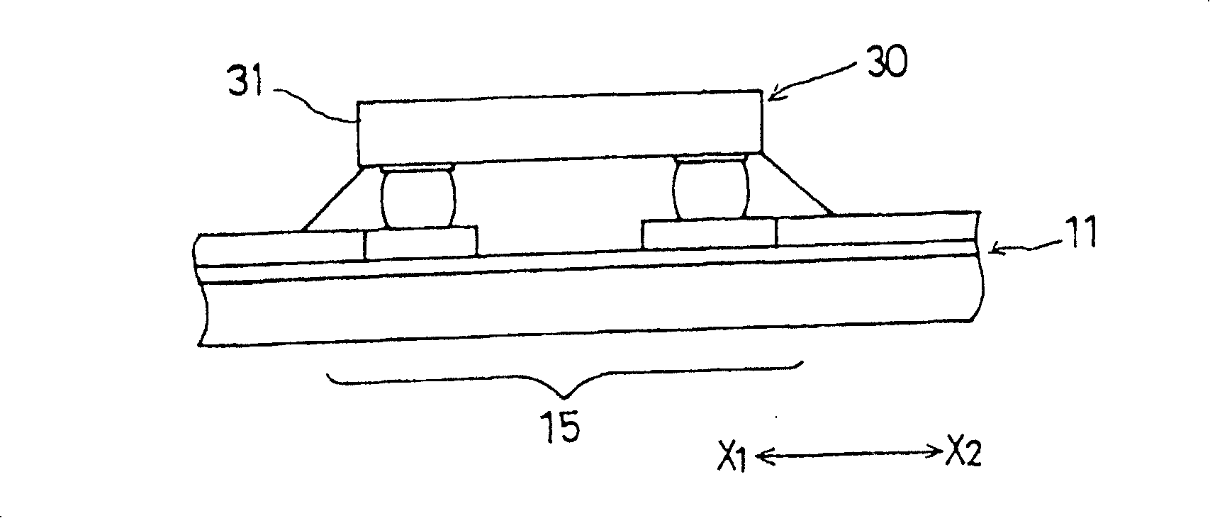
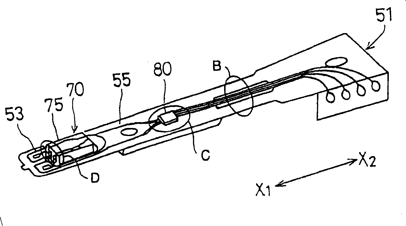
[0087] Figure 2A A perspective view of a first embodiment of a magnetic head assembly according to the present invention is shown. Figure 2B show Figure 2A A cross-sectional view of the circled portion B of the magnetic head assembly shown. Figure 2C show Figure 2A A perspective view of the circled portion C of the magnetic head assembly shown, and Figure 2D show Figure 2A A sectional view of circled portion D of the magnetic head assembly shown.
[0088] Such as Figures 2A to 2D As shown, the magnetic head assembly 50 has a magnetic head slider 70 mounted on the gimbal 52 . The gimbal 52 is arranged on the cantilever 51 along the direction X 1 Front end. The HIC chip mounting part 53 is disposed in the middle of the suspension 51, and the HIC chip 80 exposed is mounted inside the HIC chip mounting part 53 face down. In addition, the exposed magnetic head integrated circuit chip 80 is covered with a parylene polymer evaporation layer 110 formed by evaporation ...
no. 2 example
[0113] 7A is a perspective view of a second embodiment of a magnetic head assembly according to the present invention, and FIG. 7B is a sectional view of a circle portion F of the magnetic head assembly shown in FIG. 7A.
[0114] The structure of the magnetic head assembly 50A shown in FIG. 7A and Figure 2A The magnetic head assembly 50 shown is substantially the same, except for the encapsulating parylene layer 110 .
[0115] in Figures 7A and 7B with Figure 2A and 2D The same reference numerals are used for the same parts as the corresponding parts, so their explanations are omitted.
[0116] As shown in an enlarged scale in FIG. 7B , the parylene layer 110 of this embodiment covers the upper surface 81 b , the entire side 81 c , the lower surface 81 a , and the periphery of the gold bump 84 of the main chip 81 .
[0117] Especially since the upper surface 81b of the main chip body 81 and the entire side 81c are covered with the parylene layer 110, silicon particles are...
no. 3 example
[0236] 36A is a perspective view of a third embodiment of a magnetic head assembly according to the present invention, and Figure 36B It is a cross-sectional view of the circle part G of the magnetic head assembly shown in FIG. 36A, Figure 36C It is a perspective view of the circled portion H of the magnetic head assembly shown in FIG. 36A.
[0237] In the magnetic head assembly 50B shown in FIG. 36A, the magnetic head integrated circuit chip 80C has Figure 37 structure shown. Figure 37 It is a perspective view of the magnetic head IC chip 80C shown in FIGS. 36A and 36B. Such as Figure 36B As shown, the magnetic head integrated circuit chip 80C of the magnetic head assembly 50B has a main chip body 81C. Such as Figure 37 As can be seen, the rectangular upper surface 81Cb of the main chip body 81C is beveled, so that a slope 81Cd is formed between the upper surface 81Cb of the main chip body 81C and each side surface 81Cc.
[0238] use instead Figure 2D The paryle...
PUM
 Abstract
Description
Claims
Application Information
 - R&D
- Intellectual Property
- Life Sciences
- Materials
- Tech Scout
- Unparalleled Data Quality
- Higher Quality Content
- 60% Fewer Hallucinations
Browse by: Latest US Patents, China's latest patents, Technical Efficacy Thesaurus, Application Domain, Technology Topic, Popular Technical Reports.
© 2025 PatSnap. All rights reserved.Legal|Privacy policy|Modern Slavery Act Transparency Statement|Sitemap|About US| Contact US: help@patsnap.com