Method for driving plasma display panel

A technology of plasma display screen and driving method, which is applied to static indicators, instruments, etc., and can solve problems such as errors, different luminous intensities, and uneven luminous brightness of the screen.

Inactive Publication Date: 2008-08-20
PANASONIC CORP
View PDF6 Cites 0 Cited by
  • Summary
  • Abstract
  • Description
  • Claims
  • Application Information

AI Technical Summary

Problems solved by technology

[0007] In the display screen of this existing method, there is an error in the timing of discharge generation in each discharge unit according to the display state. Therefore, it is possible that the luminous intensity of each discharge unit is different, resulting in uneven luminous brightness for the entire screen. area

Method used


Image

  • Method for driving plasma display panel
  • Method for driving plasma display panel
  • Method for driving plasma display panel

Examples


Embodiment Construction

[0018] The driving method of the plasma display screen in an embodiment of the present invention will be described below with reference to the accompanying drawings.

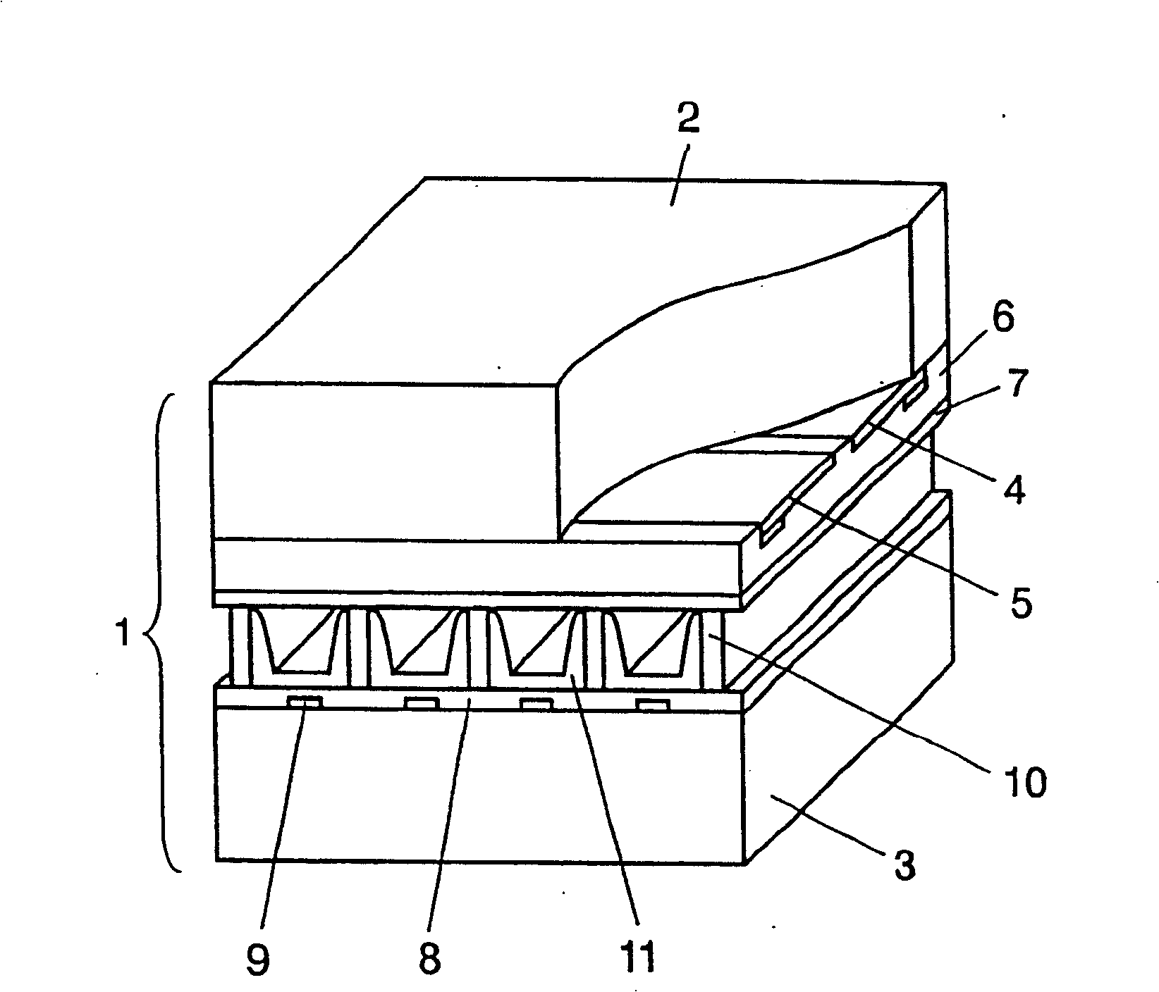
[0019] figure 1 It is a perspective view showing the main part of the display screen used in one embodiment of the present invention. The display panel 1 is configured such that a front substrate 2 and a rear substrate 3 made of glass are arranged facing each other, and a discharge space is formed therebetween. Viewed from the side of the front substrate 2, there are formed on the front substrate 2 a plurality of pairs of scan electrodes 4 and sustain electrodes 5 that are parallel to each other and form display electrodes. Dielectric layer 6 is formed to cover scan electrodes 4 and sustain electrodes 5 , and protective layer 7 is formed on dielectric layer 6 .

[0020] A plurality of data electrodes 9 covered by an insulator layer 8 are attached to the back substrate 3 , and partition walls 10 are provided on...


PUM


Abstract

Driving a plasma display panel, in which generation of a region having brightness non-uniformity can be reduced over an entire screen without changing the voltage and pulse width of sustain pulses, to enable suppression of an increase in power consumption. This driving of the plasma display panel comprises (i) an initialization period for forming a discharge cell at an intersection where a scan electrode and a sustain electrode meet a data electrode and generating initialization discharge in the cell, (ii) a writing period for generating writing discharge in the discharge cell, and (iii) a sustain period for generating sustain discharge by alternately applying sustain pulses to the scan electrode and sustain electrode of the discharge cell. The rise time of the sustain pulses applied to the scan electrode and sustain electrode during the sustain period is shortened at a frequency of once every several times.

Description

technical field [0001] The invention relates to a driving method of a plasma display screen. Background technique [0002] In a typical AC surface discharge display panel as a plasma display panel (hereinafter simply referred to as a display panel), many discharge cells are formed between a front panel and a rear panel arranged to face each other. On the front plate, multiple pairs of display electrodes consisting of a pair of scan electrodes and sustain electrodes are formed parallel to each other on the front glass substrate, and a dielectric layer and a protective layer are formed to cover the display electrodes. On the back plate, a plurality of parallel data electrodes, a dielectric layer covering the data electrodes, and a plurality of partition walls parallel to the data electrodes are respectively formed on the rear glass substrate. Then, phosphor layers are formed on both the surface of the dielectric layer and the side surfaces of the partition walls. [0003] Th...

Claims


Application Information

Patent Timeline
Patent Type & Authority Patents(China)
IPC IPC(8): G09G3/28G09G3/20G09G3/288G09G3/291G09G3/292G09G3/294G09G3/296G09G3/298
CPCG09G3/2965G09G2320/0233G09G2310/066G09G3/294
Inventor 美马邦启木村雅典木村悌一
Owner PANASONIC CORP
Why Eureka
Try Eureka