Charger with over-voltage and over-current protection and method for using the same

Inactive Publication Date: 2015-02-12
HUIZHOU KIMREE TECH
View PDF3 Cites 16 Cited by
  • Summary
  • Abstract
  • Description
  • Claims
  • Application Information

AI Technical Summary

Benefits of technology

[0026]By implementing the charger with over-voltage and over-current protection and the method for using the same of the present invention, the following advantages can be achieved: the voltage stabilizing unit can continuously provide a constant working voltage to the microcontroller unit; and when the microcontroller unit determines that the input voltage detected by the input voltage sampling unit generates over-voltage or the immediate charging current detected by the current sampling unit generates over-current, the microcontroller unit controls the switch unit to turn off, and thereby stops charging the bat

Problems solved by technology

Nowadays, most USB chargers of battery rods of electronic cigarettes on the market are weak in over-voltage protection of input ends of the USB chargers and over-current protection of output ends of the USB chargers.
The weakness of the over-voltage protection of the input ends of the USB chargers is embodied in that a typical USB charger generally has an over-voltage protection capacity of only 6V.
An input voltage that is higher than 6V will generate over-voltage, and may further burn the USB charger and a battery rod of an electronic cigarette being charged by the USB charger.
The w

Method used


Image

  • Charger with over-voltage and over-current protection and method for using the same
  • Charger with over-voltage and over-current protection and method for using the same
  • Charger with over-voltage and over-current protection and method for using the same

Examples


first embodiment

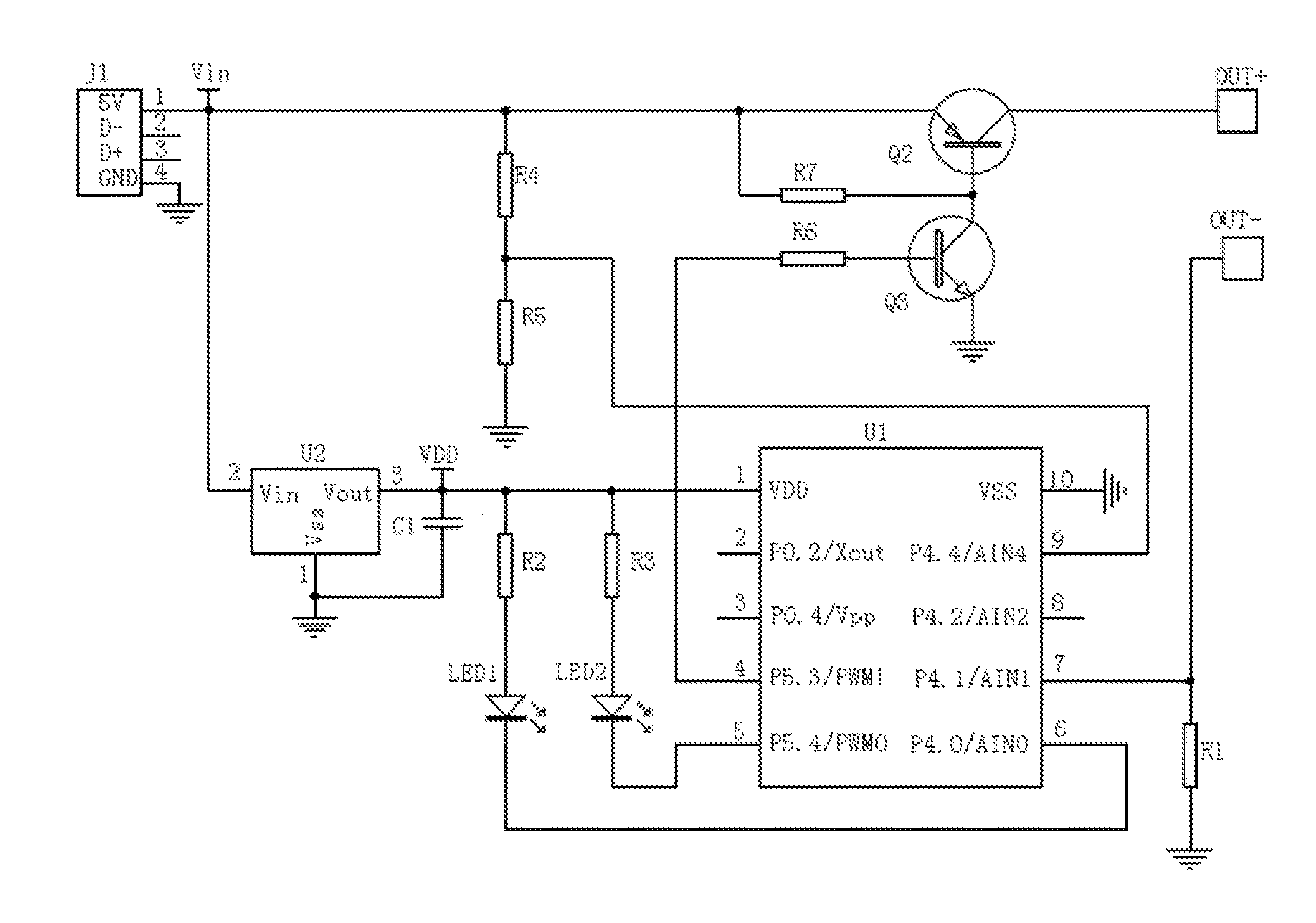
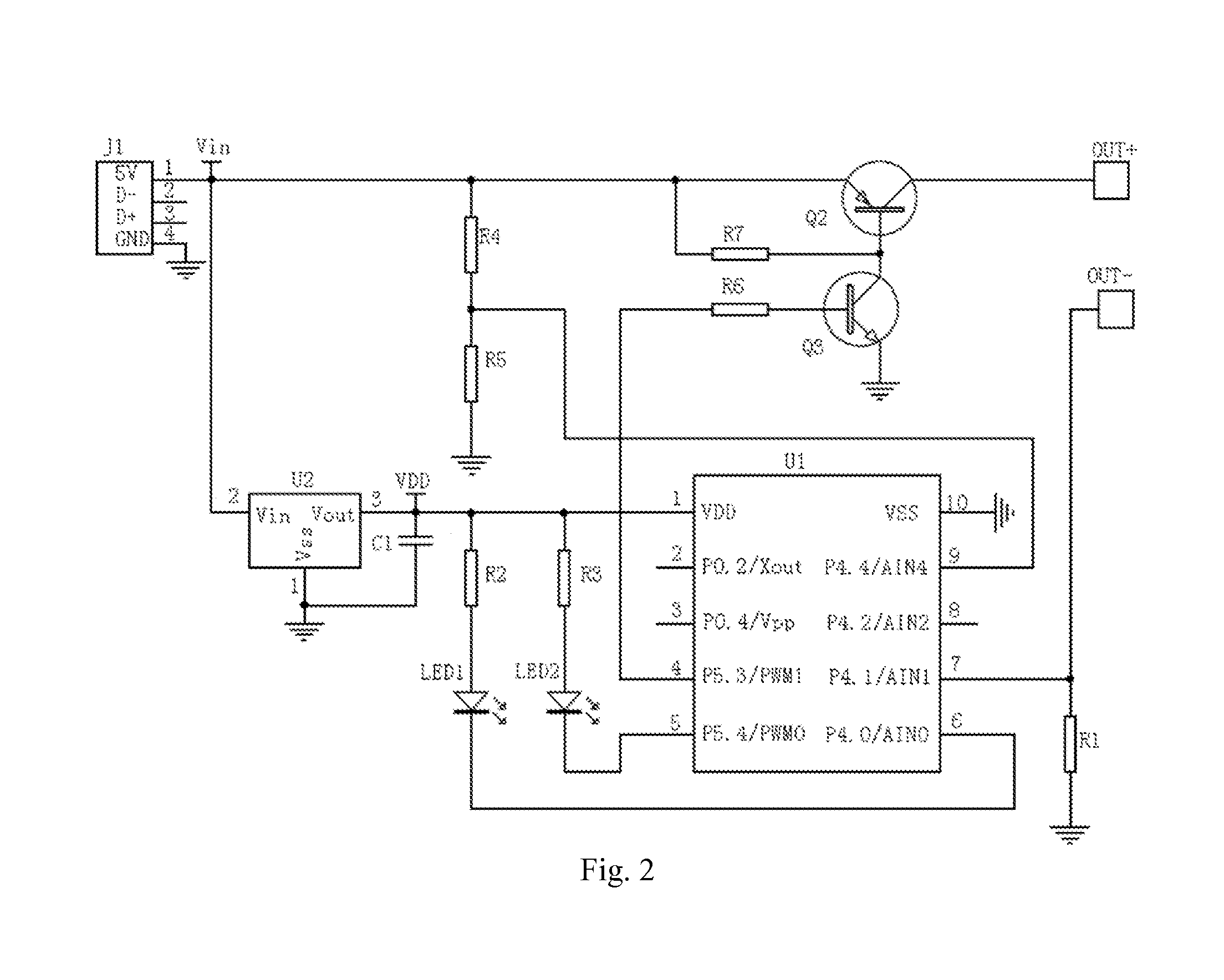
[0045]Referring to FIG. 2, which is a circuit diagram of an electronic cigarette USB charger with over-voltage and over-current protection of the present invention.

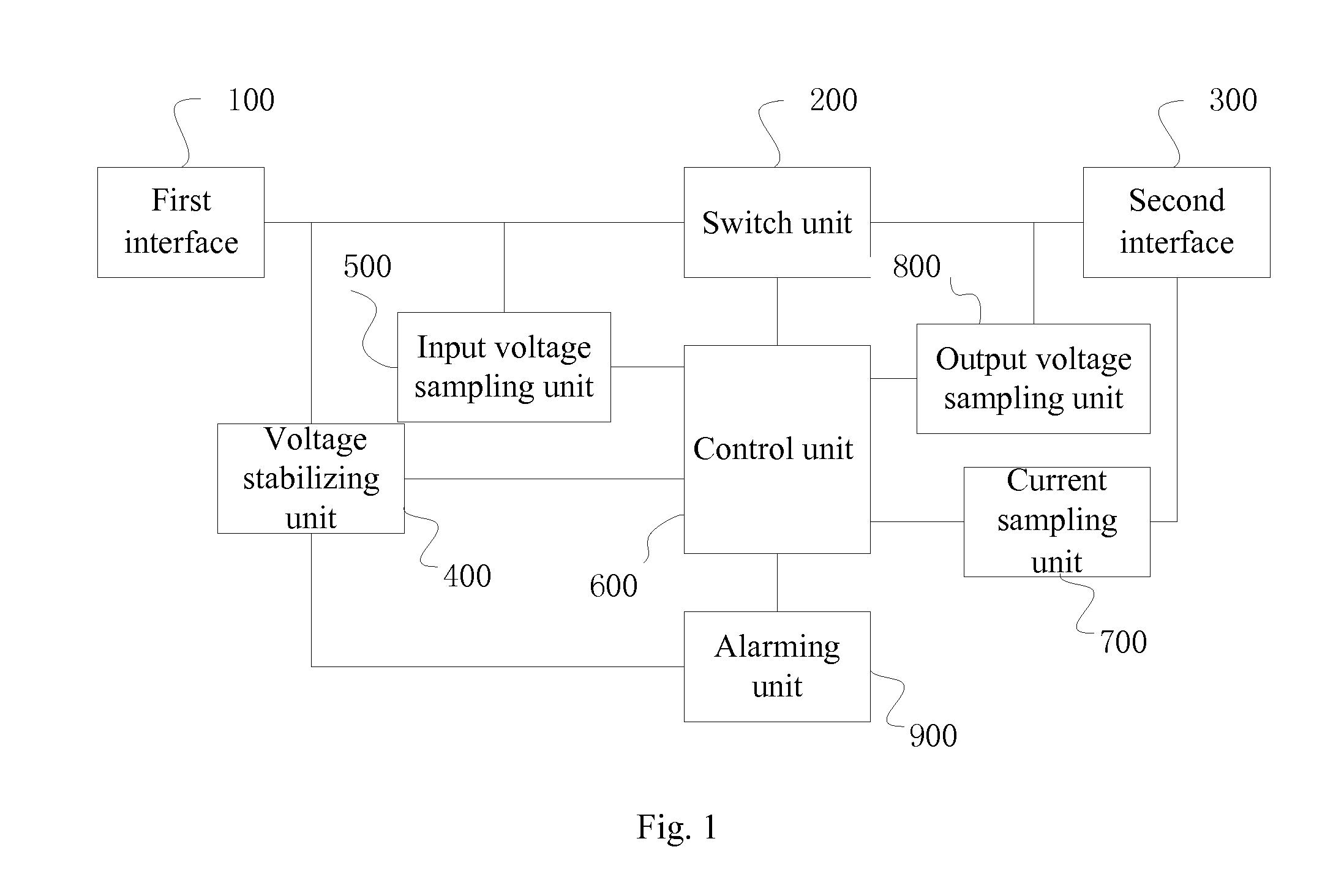
[0046]In the first embodiment, the first interface 100 is a USB interface J1.

[0047]The second interface 300 includes a positive output end OUT+ and a negative output end OUT−.

[0048]In the first embodiment, the control unit 600 includes a microprocessor U1, and the type of the microprocessor U1 is SN8P2711. The VDD pin of the microprocessor U1 is configured to receive a working voltage of the microprocessor U1. A fourth pin of the microprocessor U1 is configured to control the switch unit 200 to be turned on and turned off. A fifth pin and a sixth pin of the microprocessor U1 are configured to control the alarming unit 900 to work. A seventh pin of the microprocessor U1 is configured to receive an input signal of the current sampling unit 700. A ninth pin of the microprocessor U1 is configured to receive an input signal of...

second embodiment

[0067]Referring to FIG. 3, which is a circuit diagram of an electronic cigarette USB charger with over-voltage and over-current protection of the present invention.

[0068]The second embodiment differs from the first embodiment in that the voltage stabilizing unit 400 of the second embodiment includes a first resistor R8, a first transistor Q1, a first filtering capacitor C1, and a voltage stabilizing diode ZD1.

[0069]The collector of the first transistor Q1 is connected to the 5V voltage output end of the USB interface J1. The base of the first transistor Q1 is connected to the cathode of the voltage stabilizing diode ZD1. The anode of the voltage stabilizing diode ZD1 is grounded. The emitter of the first transistor Q1 is connected to VDD pin of the microprocessor U1.

[0070]One end of the first capacitor C1 is connected to the emitter of the first transistor Q1, and the other end of the first capacitor C1 is grounded. One end of the first resistor R8 is connected to the base of the fi...

third embodiment

[0072]Referring to FIG. 4, which is a circuit diagram of an electronic cigarette USB charger with over-voltage and over-current protection of the present invention.

[0073]Compared with the second embodiment, the third embodiment adds the output voltage sampling unit 800. The output voltage sampling unit 800 includes a third divider resistor R10, a fourth divider resistor R11, a fourth filtering capacitor C4, and a fifth filtering capacitor C5.

[0074]One end of the third divider resistor R10 is connected to the positive output end OUT+ of the second interface 300, and the other end of the third divider resistor R10 is connected to one end of the fourth divider resistor R11 and the eighth pin of the microprocessor U1. The other end of the fourth divider resistor R11 is grounded. The fifth filtering capacitor C5 is connected in parallel with the fourth divider resistor R11. One end of the fourth filtering capacitor C4 is connected to the collector of the second transistor Q2, and the oth...


PUM


Abstract

A charger with over-voltage and over-current protection and a method for using the same are provided. The charger comprises a first interface, a second interface, a voltage stabilizing unit, a control unit, an input voltage sampling unit, a switch unit, and a current sampling unit. The voltage stabilizing unit receives an input voltage of an external power supply and provides a constant working voltage to the control unit. The input voltage sampling unit detects the input voltage real-timely. The current sampling unit detects charging current of the battery rod real-timely. The control unit determines whether the input voltage detected by the input voltage sampling unit generates over-voltage or not, or determines whether the charging current detected by the current sampling unit generates over-current or not, and controls the switch unit to turn on or turn off according to the determination results.

Description

CROSS-REFERENCE TO RELATED APPLICATIONS[0001]This non-provisional application claims priorities under 35 U.S.C. §119(a) on Patent Application No. 201320488792.2 filed in P.R. China on Aug. 9, 2013, the entire contents of which are hereby incorporated by reference.FIELD OF THE INVENTION[0002]The present invention relates to the field of electronic cigarettes, and more particularly, relates to a charger with over-voltage and over-current protection and a method for using the same.BACKGROUND OF THE INVENTION[0003]Nowadays, most USB chargers of battery rods of electronic cigarettes on the market are weak in over-voltage protection of input ends of the USB chargers and over-current protection of output ends of the USB chargers.[0004]The weakness of the over-voltage protection of the input ends of the USB chargers is embodied in that a typical USB charger generally has an over-voltage protection capacity of only 6V. An input voltage that is higher than 6V will generate over-voltage, and m...

Claims


Application Information

Patent Timeline
IPC IPC(8): H02H3/10H02J7/00A24F40/90
CPCH02H3/10H02J2007/0039H02J7/0031H02H7/18H02J7/00302H02J7/00304H02J7/00306H02J7/00308H02J7/007A24F40/90H02J7/04H02M3/315
Inventor XIANG, ZHIYONG
Owner HUIZHOU KIMREE TECH
Why Eureka
Try Eureka