Automatic Power Generation Control in Micro-Grids

a micro-grid and power generation technology, applied in the direction of electric generator control, process and machine control, instruments, etc., can solve the problems of reducing the quality of power supply to the pds, reducing the plug-in capability of the micro-grid into the pds, and providing an extra burden to the pds

Active Publication Date: 2017-03-16
MITSUBISHI ELECTRIC RES LAB INC
View PDF3 Cites 21 Cited by
  • Summary
  • Abstract
  • Description
  • Claims
  • Application Information

AI Technical Summary

Benefits of technology

[0007]It is an object of some embodiments of the invention to provide a system and a method for controlling the generator of the micro-grid resulting in substantially constant voltage on a point of common coupling (PCC) of the micro-grid to the power distribution system (PDS). It is another object of some embodiments to provide such a method that controls the generator using local information available to the controller of the micro-grid. Such information can include results of power flow analysis based on the measurements on the micro-grid and / or a link connecting the PCC with the bus of PDS. Such a local control enables plug-and-play capability of the micro-grid connected to the PDS that allows connecting a micro-grid to the PDS without modification of the operation of the PDS beyond the connection link.

Problems solved by technology

Such instability reduces the quality of power supply to the PDS, and requires the PDS to control the variations of the voltage supplied by the micro-grid.
However, maintaining the stable voltage supply to the PDS requires sophisticated measurements of the power flow on the entire PDS and the micro-grid, which complicates plugin capability of the micro-grid into the PDS.
Controlling the micro-grid with the feedback signal determined by PDS provides an extra burden for the PDS and reduces plug-and-play capabilities of the micro-grids.
In addition, providing voltage-control ancillary service by maintaining power quality is a challenging task for micro-grids, because these small-scale power systems are typically managed by droop controllers.
System state changes make PDS operators unable to predict power quality in a power distribution network with micro-grids.

Method used


Image

  • Automatic Power Generation Control in Micro-Grids
  • Automatic Power Generation Control in Micro-Grids
  • Automatic Power Generation Control in Micro-Grids

Examples


Embodiment Construction

[0019]Overview of Micro-Grid Connected to Power Distribution System

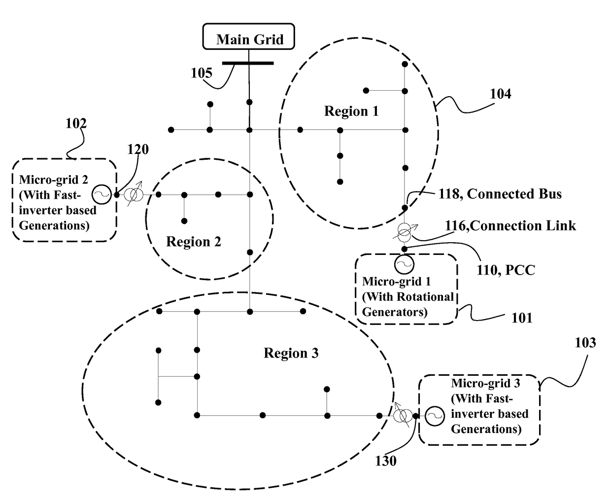
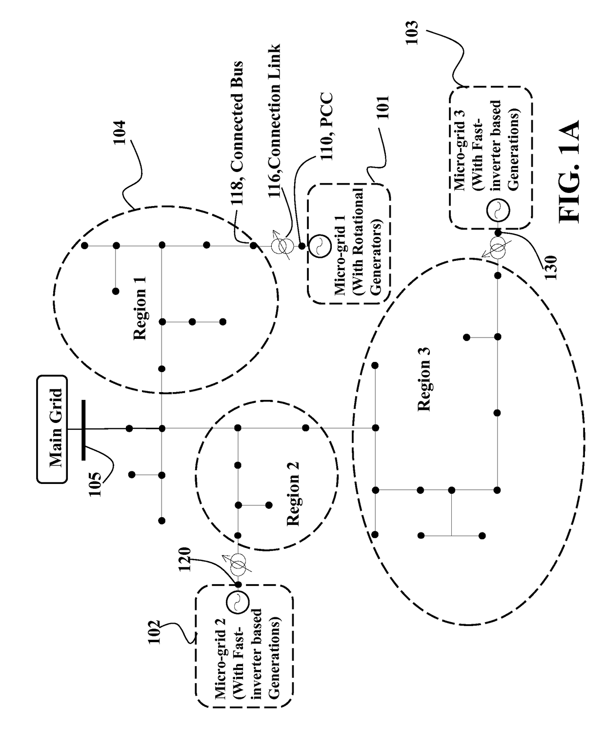
[0020]FIG. 1A shows an example of a micro-grid, e.g., a micro-grid 101, 102 or 103, connected to a power distribution system (PDS) 104 according to some embodiments of an invention. The PDS is connected to the main grid (i.e. transmission system) through a bus 105. Three micro-grids are connected to the PDS through a point of common coupling (PCC), for example, buses 110, 120, and 130 respectively. Therefore, each micro-grid connects to the power distribution network through its PCC at bus i to a load bus j. A link connects the PCC of each micro-grid with a bus of the PDS. For example, the PCC 110 is connected with the first bus 118 on the PDS through a connection link. The connection link can include, for example, a step-up transformer 116 or transmission line to connect the micro-grid to the connected bus 118.

[0021]In some implementations, the taps of each transformer are used to regulate the voltage at a point of ...


PUM


Abstract

A method controls a micro-grid connected to a power distribution system. The method determines parameters of a model of dynamics of the micro-grid using measurements of power flow at a point of common coupling (PCC) of the micro-grid with the power distribution system. The model is exponentially stable on a voltage set-point at the PCC and the method determines, using the parameters of the model, an amount of reactive power required to maintain the voltage at the PCC asymptotically stable on the voltage set-point. Next, the method controls a generator of the micro-grid to produce the amount of reactive power.

Description

FIELD OF THE INVENTION[0001]The present invention relates generally to electric power systems, and more particularly to controlling a micro-grid connected to a power distribution system.BACKGROUND OF THE INVENTION[0002]A micro-grid is a localized grouping of power generation, storage, and loads that can be connected to the power distribution system (PDS) to provide an additional control layer integrating intermittent renewable energy resources to the power distribution system. From the point of view of a PDS, a connected micro-grid can be controlled as if it is one entity.[0003]A PDS usually treats the micro-grid as a positive or negative load due to unstable voltage on the micro-grid caused by load or generation variations. Such instability reduces the quality of power supply to the PDS, and requires the PDS to control the variations of the voltage supplied by the micro-grid. However, maintaining the stable voltage supply to the PDS requires sophisticated measurements of the power ...

Claims


Application Information

Patent Timeline
Patent Type & Authority Applications(United States)
IPC IPC(8): H02J3/00G05B17/02H02P9/10
CPCH02J3/00G05B17/02H02P9/105H02J3/06Y02P80/14H02J2203/20H02J2310/10Y04S40/20Y04S20/00Y02B90/20Y02E60/00
Inventor SUN, HONGBOWANG, ZHAO
Owner MITSUBISHI ELECTRIC RES LAB INC
Why Eureka
Try Eureka