Armature coil winding method

A technology of armature coil and winding method, which is applied in the field of armature coil winding machine, and can solve problems such as new coil slack

Inactive Publication Date: 2008-09-03
PANASONIC CORP
View PDF4 Cites 0 Cited by
  • Summary
  • Abstract
  • Description
  • Claims
  • Application Information

AI Technical Summary

Problems solved by technology

However, the winding of the armature coil is done in a continuous manner, and problems such as slack in the new coil occur every time a coil is wound

Method used


Image

  • Armature coil winding method
  • Armature coil winding method
  • Armature coil winding method

Examples


no. 1 example

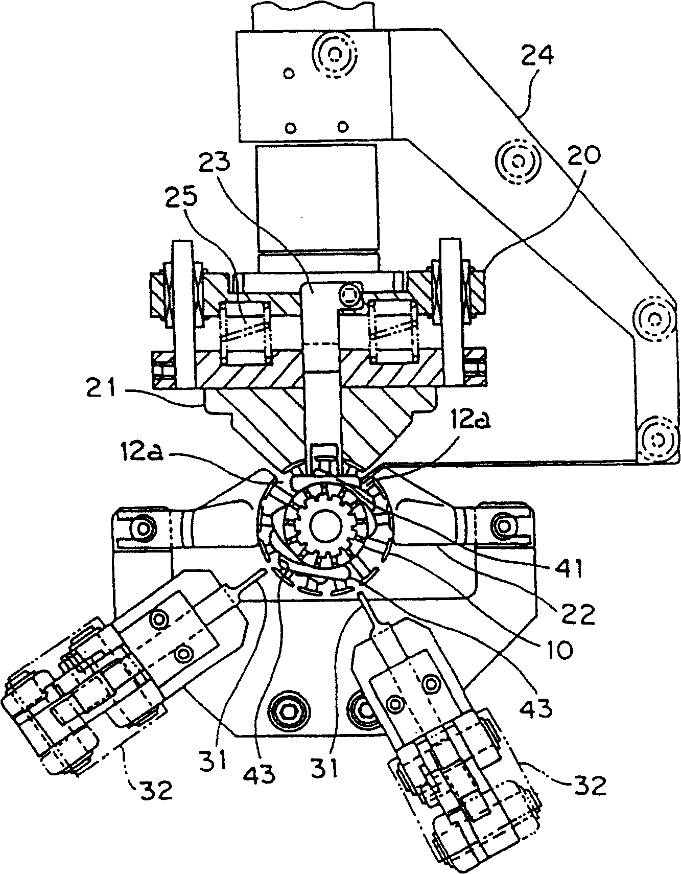
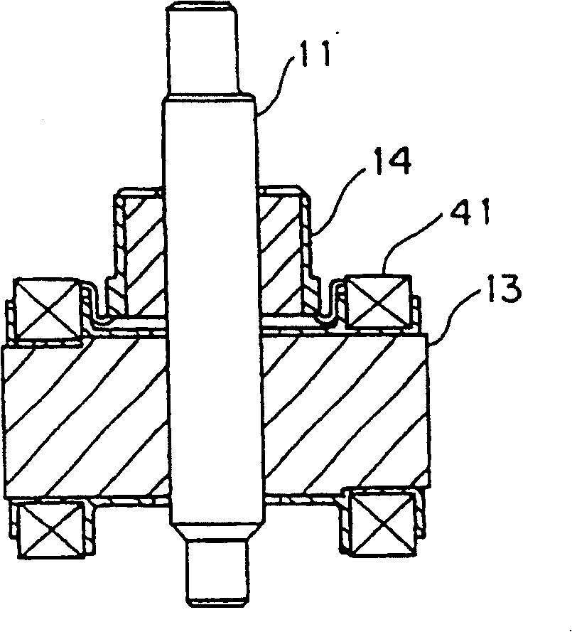
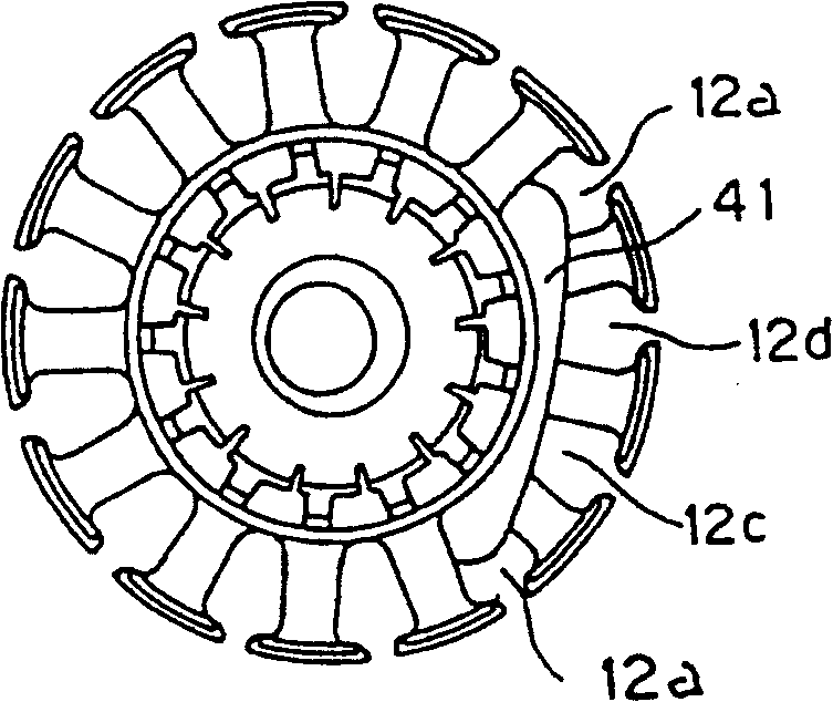
[0027] Fig. 5(a) is a top view of an embodiment of the winding die mechanism of the present invention, and Fig. 5(b) is a front view of the winding die mechanism. In FIG. 5, an armature assembly 10 is supported by a shaft 11, which constitutes an armature armature core assembly 10, and moves periodically in its rotational direction. In a winding process, a winding mold sliding seat makes a winding mold 20 closely contact with the armature core assembly 10, so that a fixed mold 21 and a side mold 22 constituting the winding mold 20 are formed along an outer circumference. Positioning, thus forming a bobbin, it allows the wire to be wound only in the slots 12a, 12a to be wound, as shown in FIG. 5 . In addition to these traditional bobbin structures, a movable mold 23 is also arranged in the fixed mold, and the movable mold can move toward its center along the two end faces 16 of an armature iron core, and the movable mold whose position can be controlled according to needs forms...

no. 2 example

[0031] Image 6 It is a plan view of an embodiment of the coil shaping mechanism of the present invention. The coil shaping mechanism is composed of a coil shaping blade 31 whose width is substantially equal to the width of the slot opening 17 and a shaping driving source 32 capable of controlling the shaping pressure. When the position of the coil shaping blade is arranged to correspond to the position corresponding to the groove 12b, 12b just subjected to winding with respect to the mold slide, it is possible to make the coil 43 reshaping in the next groove to be wound with respect to the winding. The winding space is secured synchronously with the wire process.

[0032] Figure 7 is a top view of another embodiment of the coil shaping mechanism. When the position of the coil shaping blade relative to the die slide is set to correspond to the next slot 12c, 12c to be wound, it is possible to ensure that the coil is shaped synchronously with the winding process by shaping th...


PUM


Abstract

In order to realize thinner armature, a winding coil with high density, a winding machine which limits an end of the coil within the limited space and a method of using the winding machine for the wire winding are provided. The armature coil winding machine is used to wind a first coil between any two slots of an armature iron core. At the same time, an active mode is used for limiting the position of the coil end between the two slots for the wire winding. The first coil in every slot is shaped. Then, in the same armature, the armature coil winding machine is used to coil and shape another coil between any two slots except the two slots of the first coil. At the same time, an active mode is used for limiting the position of the coil end between the other two slots of the armature iron core. Other coils are repeatedly winded and shaped for a plurality of times. The armature coil winding machine is used for alternatively implementing the coil shaping and the coil winding.

Description

[0001] This application is a divisional application with the application number 98805355.1, the application date being April 30, 1998, and the invention name being "armature coil winding machine and winding method". technical field [0002] The invention relates to an armature coil winding machine and a high-density winding method for coils in an armature iron core assembly for a motor. Background technique [0003] In recent years, how to make the motor thinner has become an important basic issue for industrial products that use the motor as the main mechanism. Among the parts of the motor, the armature is one of the biggest obstacles to the thinning of the motor. [0004] Figure 8 It is a schematic diagram of a traditional winding machine, Figure 9 A conventional armature core assembly with a coil wound therein is shown. [0005] This traditional winding machine winds coils in slots 12a, 12a along a fixed winding die 21 with a flywheel 24, and the end wire 42 of the co...

Claims


Application Information

Patent Timeline
Patent Type & Authority Patents(China)
IPC IPC(8): H02K15/09
CPCH02K15/09Y10T29/49009Y10T29/49012Y10T29/49071Y10T29/49073Y10T29/5141Y10T29/53143Y10T29/53157
Inventor 山崎昭彦冈元学木村和夫
Owner PANASONIC CORP
Why Eureka
Try Eureka