Explosion-proof shell, manufacturing method thereof and battery with explosion-proof shell

A technology of explosion-proof casing and manufacturing method, which is applied to large-sized batteries/battery packs, small-sized batteries/battery packs, battery pack components, etc., and can solve the problem of uneconomical and reliable manufacturing methods for engraving and insufficient deformation Space explosion-proof pressure relief, explosion-proof structure takes up a lot of space, etc., to achieve the effect of facilitating automated production, ensuring effective space, and low maintenance costs

Pending Publication Date: 2022-05-31
CHANGZHOU MICROBAT TECH CO LTD
View PDF0 Cites 0 Cited by
  • Summary
  • Abstract
  • Description
  • Claims
  • Application Information

AI Technical Summary

Problems solved by technology

[0005] The technical problem to be solved by the present invention is: in order to solve the problem that the traditional laminated explosion-proof structure occupies a large space and is difficult to install in a micro battery; There is no economical and reliable manufacturing method for the groove, and due to the limitation of the use environment, it is impossible to provide sufficient deformation space to realize the explosion-proof pressure relief function. The invention provides an explosion-proof casing and its manufacturing method and a battery with an explosion-proof casing. The explosion-proof casing Easy to manufacture, no need to add additional structural space, simple manufacturing process, low maintenance cost, explosion-proof pressure relief function, and high safety performance

Method used


Image

  • Explosion-proof shell, manufacturing method thereof and battery with explosion-proof shell
  • Explosion-proof shell, manufacturing method thereof and battery with explosion-proof shell
  • Explosion-proof shell, manufacturing method thereof and battery with explosion-proof shell

Examples


Embodiment 1

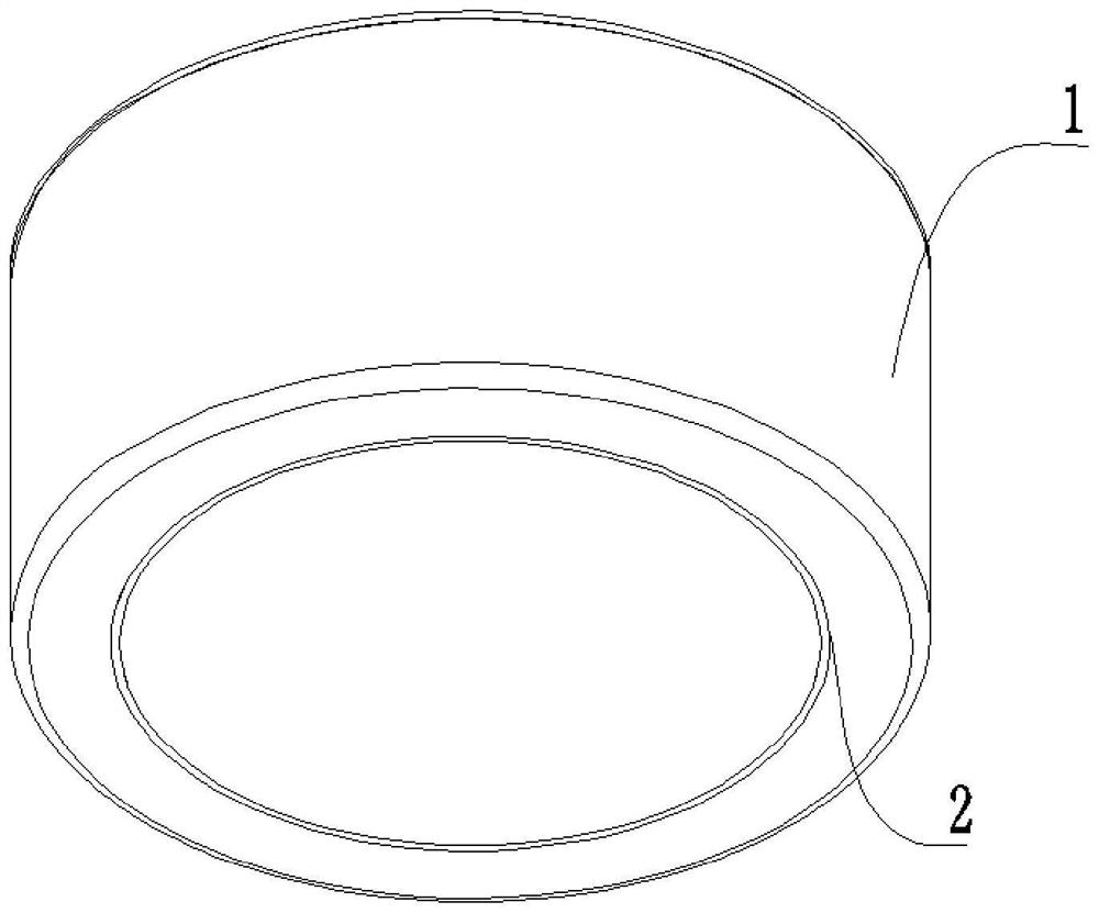
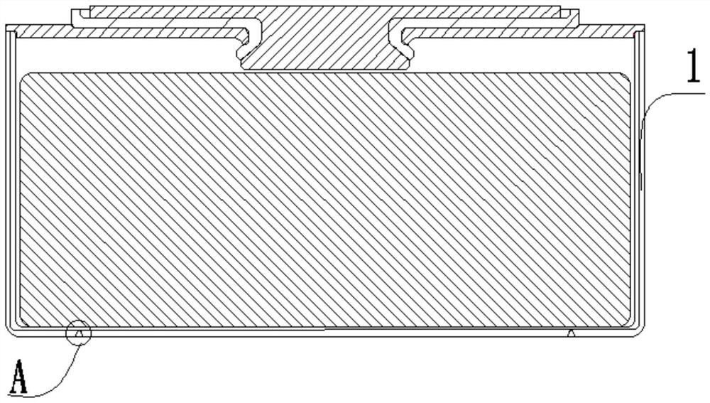
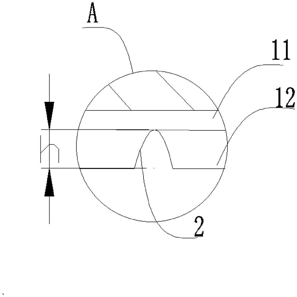
[0041] Such as Figure 1-3 As shown, it is Embodiment 1 of the present invention, an explosion-proof enclosure, comprising: a housing body 1, the housing body 1 is a double-layer composite structure, the double-layer composite structure includes an inner layer 11 and an outer layer 12, and the inner layer 11 and the outer layer The layers 12 are tightly pressed together; the outer layer 12 on one side of the shell body 1 is provided with an explosion-proof groove 2, which extends along the circumferential direction of the shell body 1, and the explosion-proof groove 2 is ring-shaped, and the depth h of the explosion-proof groove 2 is equal to that of the outer layer 12 thickness, the bottom of the explosion-proof groove 2 is provided with an opening, and the surface part of the inner layer 11 is exposed to the opening; the normal working pressure in the housing body 1 is set as pressure P, if the pressure in the housing body 1 is greater than the pressure P, The inner layer 11...

Embodiment 2

[0052] Such as Figure 4-6 As shown, it is the second embodiment of the present invention. The difference from the first embodiment is that the outer layer 12 on one side of the shell body 1 is also provided with a first weakened portion 3 and a second weakened portion 4. The first weakened portion The part 3 and the second weakened part 4 both extend along the circumferential direction of the shell body 1, the first weakened part 3 and the second weakened part 4 are both ring-shaped, and the first weakened part 3 surrounds the second weakened part 4; the explosion-proof groove 2 is arranged on the second Between the first weakened portion 3 and the second weakened portion 4 . The explosion-proof groove 2 is directly exposed, and is easily damaged and deformed by collision, extrusion, etc. during production, transportation and use. By hiding the explosion-proof groove 2 between the first weakened part 3 and the second weakened part 4, it can avoid damage caused by collision o...

Embodiment 2

[0055] The manufacturing method of making embodiment two explosion-proof casing comprises the following steps:

[0056] S1: Select the preliminarily formed shell body 1, which is a double-layer composite structure, which includes an inner layer 11 and an outer layer 12, and the inner layer 11 and the outer layer 12 are tightly pressed together.

[0057] S2: The first weakened part 3 and the second weakened part 4 are formed by thinning the outer layer 12 on one side of the shell body 1, and both the first weakened part 3 and the second weakened part 4 extend along the circumferential direction of the shell body 1, Both the first weakened part 3 and the second weakened part 4 are annular, the first weakened part 3 surrounds the second weakened part 4, and an explosion-proof groove 2 is opened between the first weakened part 3 and the second weakened part 4, and the explosion-proof groove 2 It is annular, and the depth h of the explosion-proof groove 2 is equal to the thickness ...


PUM


Abstract

The invention relates to the technical field of batteries, in particular to an explosion-proof shell and a manufacturing method thereof and a battery with the explosion-proof shell, the explosion-proof shell comprises a shell body, the shell body is of a double-layer composite structure, the double-layer composite structure comprises an inner layer and an outer layer, and the inner layer and the outer layer are tightly pressed; an annular anti-explosion groove is formed in the outer layer of the surface of one side of the shell body, the depth h of the anti-explosion groove is equal to the thickness of the outer layer, an opening is formed in the bottom of the anti-explosion groove, and the surface of the inner layer is partially exposed out of the opening; the pressure intensity of normal work in the shell body is set to be the pressure intensity P, if the pressure intensity in the shell body is larger than the pressure intensity P, the inner layer is extruded and deformed to generate cracks, and the cracks are communicated with the opening. The invention provides an explosion-proof shell, a manufacturing method thereof and a battery with the explosion-proof shell. The explosion-proof shell is easy to manufacture, does not need to add extra structural space, is simple in manufacturing process and low in maintenance cost, has an explosion-proof pressure relief function and is high in safety performance.

Description

technical field [0001] The invention relates to the technical field of batteries, in particular to an explosion-proof casing, a manufacturing method thereof and a battery with the explosion-proof casing. Background technique [0002] Currently, batteries on the market are equipped with explosion-proof structures to ensure that the internal air pressure rises excessively during long-term use or thermal runaway in order to avoid internal thermal runaway caused by internal thermal runaway and explosion due to internal manufacturing defects or user abuse. The pressure can be released in time to prevent the battery from exploding, thereby protecting personal and property safety. [0003] At present, typical explosion-proof valve designs can be divided into the following two categories: one is a laminated explosion-proof pressure relief structure, which is generally used in the design of cylindrical lithium-ion battery cover plates, and generally has the functions of cutting off a...

Claims


Application Information

Patent Timeline
Patent Type & Authority Applications(China)
IPC IPC(8): H01M50/10H01M50/124H01M50/143H01M50/147H01M50/30
CPCH01M50/30H01M50/10H01M50/147H01M50/143H01M50/124Y02E60/10
Inventor 薛云峰柳瑞罗家文
Owner CHANGZHOU MICROBAT TECH CO LTD
Why Eureka
Try Eureka