Production for light conductive board

A manufacturing method and technology of a light guide plate, applied in the direction of light guides, optics, optical components, etc., can solve the problem of low precision of the light guide plate, and achieve the effect of improving the uniform light effect

Inactive Publication Date: 2008-09-17
HONG FU JIN PRECISION IND (SHENZHEN) CO LTD +1
View PDF3 Cites 1 Cited by
  • Summary
  • Abstract
  • Description
  • Claims
  • Application Information

AI Technical Summary

Problems solved by technology

[0005] In order to overcome the problem of low precision of the manufacturing method of the light guide plate in the prior art, the present invention provides a manufacturing method of the light guide plate with high precision

Method used


Image

  • Production for light conductive board
  • Production for light conductive board
  • Production for light conductive board

Examples


Embodiment Construction

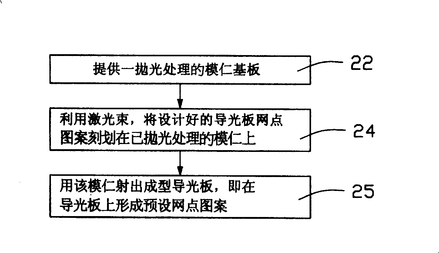
[0012] see figure 2 , is a flow chart of the manufacturing method of the light guide plate of the present invention, comprising the following steps: providing a polished mold core substrate (step 22); using a laser beam, marking the designed light guide plate dot pattern on the polished mold Form a light guide plate mold core on the core substrate (step 24); use the mold core to injection mold the light guide plate, that is, form a preset dot pattern on the light guide plate (step 25).

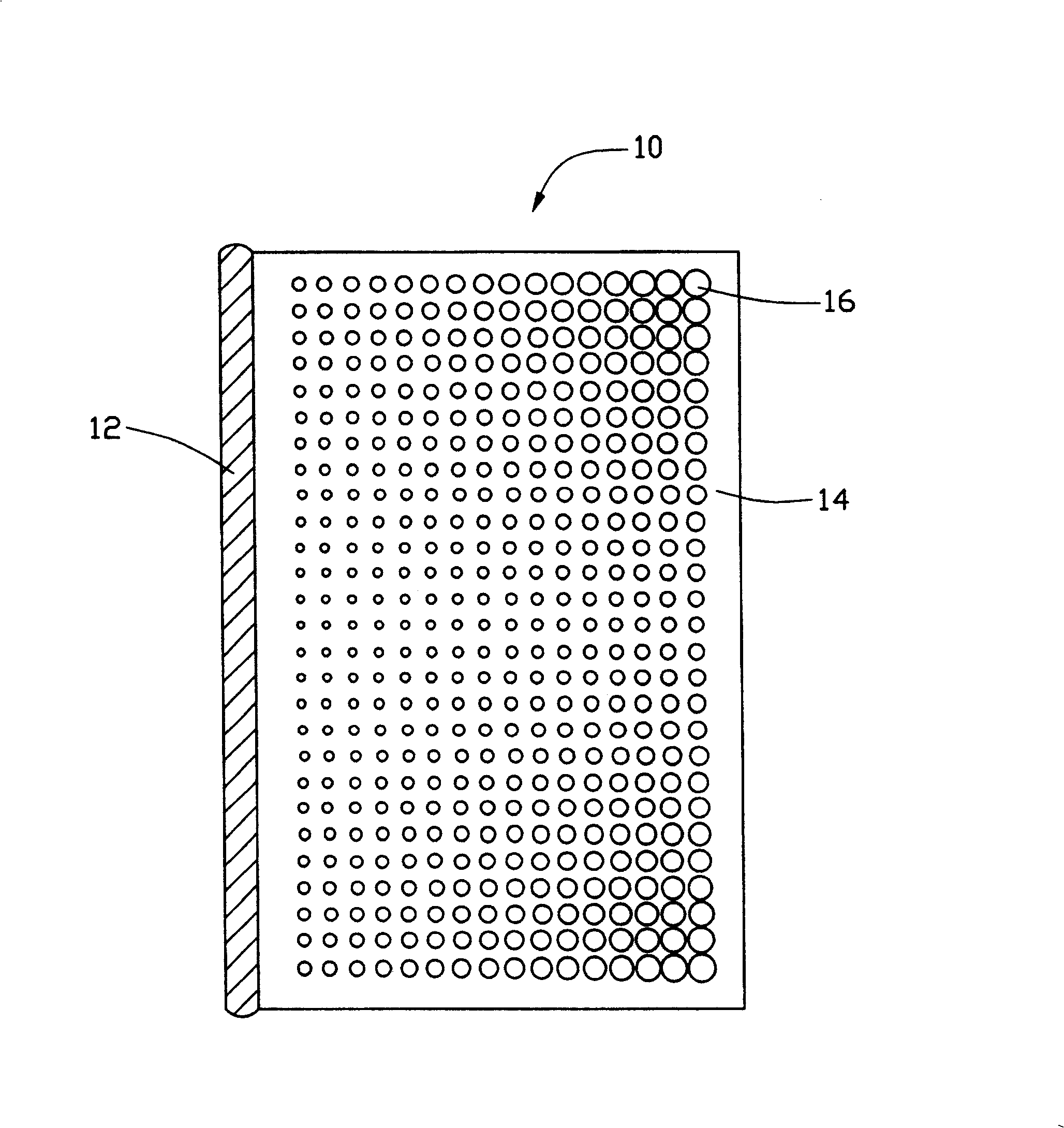
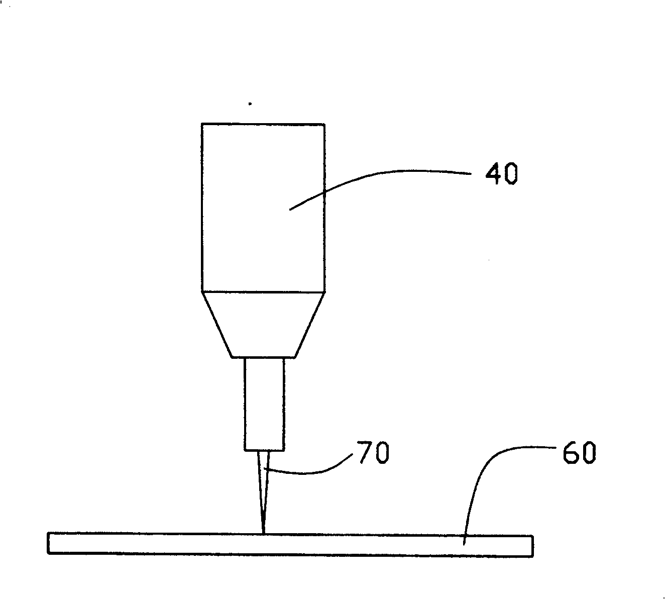
[0013] see image 3 , is a schematic diagram of the process of laser scribing the mold core substrate in the light guide plate manufacturing method of the present invention. Under program control, the laser emitting system 40 emits laser light 70 to mark dots on the mold core substrate 60 . According to the designed dot pattern of the light guide plate, in a specific small area of ​​the mold core, the laser with the same power and beam radius is used to mark the dots, so as to ensure the con...


PUM

PropertyMeasurementUnit
wavelengthaaaaaaaaaa

Abstract

A method for preparing lightguide plate includes providing a mould baseboard, utilizing laser beam to etch designed lattice point pattern for light guide plate on the mould baseboard to form light guide plate mould, forming shaped lightguide plate by ejection with the mould to have present lattice point pattern prepared on the lightguide plate.

Description

【Technical field】 [0001] The invention relates to a method for manufacturing a light guide plate, in particular to a method for manufacturing a light guide plate with a dot structure. 【Background technique】 [0002] The internal light source in a liquid crystal display (LCD) is usually combined with a light guide plate to form a backlight source to illuminate the liquid crystal panel. Since the light source is usually arranged on one side of the light guide plate to emit light, the light generated on the light emitting surface of the light guide plate will not be very uniform, especially near the light source. In order to solve the problem of uneven light emission, in the prior art, a plurality of dots are arranged on the bottom surface of the light guide plate to scatter the light transmitted in the light guide plate, so that the light emitting surface of the light guide plate emits uniform light. [0003] A kind of prior art can refer to Chinese patent application No. 001...

Claims


Application Information

Patent Timeline
Patent Type & Authority Patents(China)
IPC IPC(8): G02F1/1335G02B6/00
Inventor 蔡坤荣
Owner HONG FU JIN PRECISION IND (SHENZHEN) CO LTD
Why Eureka
Try Eureka