Eureka AIR delivers breakthrough ideas for toughest innovation challenges, trusted by R&D personnel around the world.

Ball spline

A technology of ball splines and balls, applied in bearings, linear motion bearings, bearing components, etc., can solve the problems of reduced section moment of inertia and unfavorable bending rigidity of spline shafts, so as to ensure bending rigidity, improve rigidity, and reduce The effect of manufacturing costs

Active Publication Date: 2008-09-24
THK CO LTD
View PDF8 Cites 0 Cited by
  • Summary
  • Abstract
  • Description
  • Claims
  • Application Information

AI Technical Summary

Problems solved by technology

On the other hand, if the maximum diameter of a spline shaft with a substantially rectangular cross-section is the same as that of a spline shaft with a circular cross-section, the cross-sectional area has to be smaller because the moment of inertia of the cross-section is reduced only by this part. , so it is unfavorable to the bending rigidity of the spline shaft

Method used


Image

  • Ball spline
  • Ball spline
  • Ball spline

Examples


Embodiment Construction

[0032] Next, the ball spline of the present invention will be described in detail using the drawings.

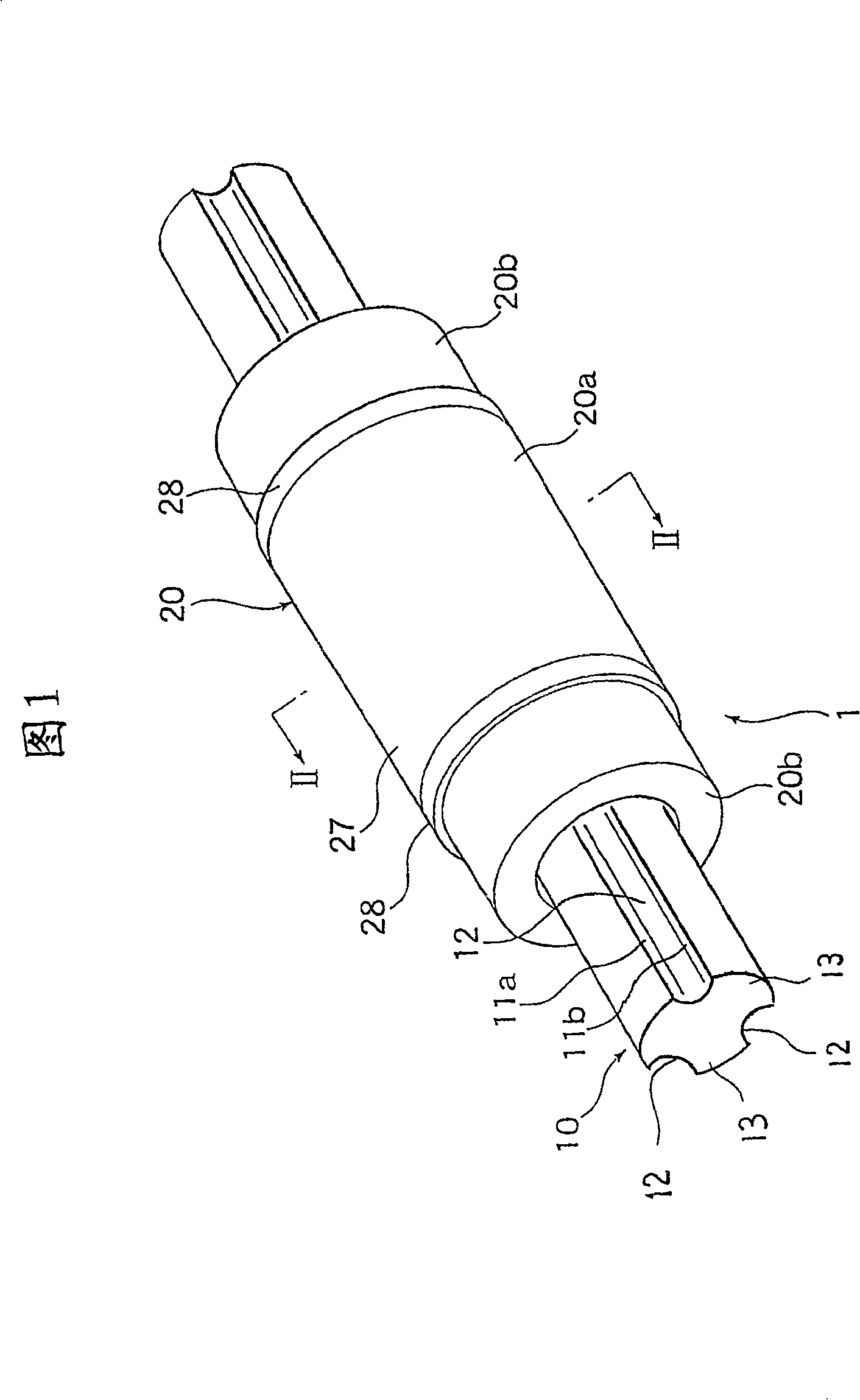
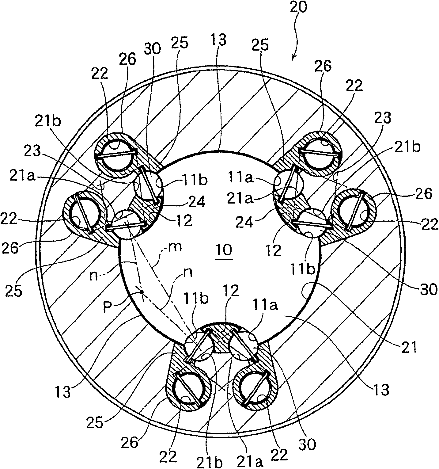
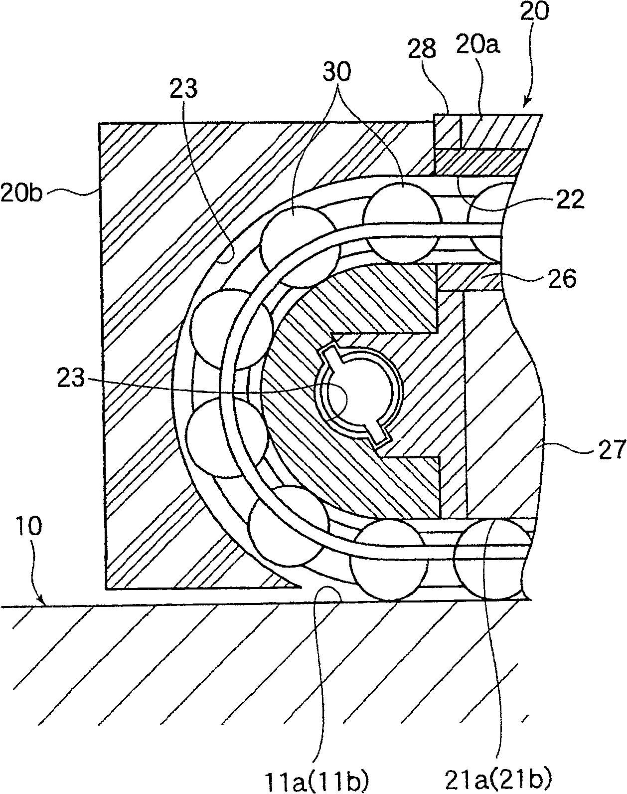
[0033] Figure 1 and figure 2 It is a front sectional view showing the first embodiment of the ball spline to which the present invention is applied. The ball spline 1 is composed of a spline shaft 10 and a spline nut 20, the spline shaft 10 is formed with a plurality of ball rolling surfaces 11a, 11b along the length direction; The hole 21 is formed in a substantially cylindrical shape.

[0034]The spline shaft 10 has a substantially circular cross-section, and three torque transmission grooves 12 are formed on its outer peripheral surface in the longitudinal direction. These torque transmission grooves 12 are arranged to divide the outer peripheral surface of the spline shaft 10 into thirds, and each torque transmission groove 12 is provided so as to cut the outer peripheral surface of the spline shaft 10 into an arc shape. On the outer peripheral surface of the spline s...


PUM


Abstract

A ball spline enabling the easy machining of a spline shaft by drawing and manufacturable at low cost, comprising the spline shaft in which multiple lines of ball rolling faces are formed along the longitudinal direction and a spline nut having a hollow hole for inserting the spline shaft therein, formed in a generally cylindrical shape, having load rolling faces opposed to the ball rolling faces of the spline shaft which are formed in the inner peripheral surface of the hollow hole, and installed on the spline shaft through a large number of balls. The spline shaft is formed in a generally circular shape in cross section. Multiple lines of torque transmission grooves along the longitudinal direction are formed at equal intervals around the spline shaft, and the ball rolling faces are formed on the lateral both sides of these torque transmission grooves. Also, a distance between a pair of ball rows rolling on both sides of the land parts of the spline shaft is set larger than a distance between a pair of ball rows rolling on both sides of the torque transmission grooves.

Description

technical field [0001] The present invention relates to a combination of a spline shaft and a spline nut that can move relatively freely linearly through a plurality of balls, and is used in machine tools or linear guides in various industrial machines, torque transmission parts in industrial robots, etc. Specifically, the ball spline relates to a technique for efficiently transmitting torque between the above-mentioned spline shaft and the spline nut. Background technique [0002] Patent Document 1: JP-A-58-137616 [0003] Patent Document 2: Publication No. 61-179414 of Shikaizhao [0004] Conventionally, ball splines disclosed in JP-A-58-137616 and JP-A-61-179414 are known as such ball splines. These ball splines are composed of a spline shaft and a spline nut, the spline shaft has a plurality of ball rolling surfaces extending along the length direction; the spline nut is assembled on the above-mentioned spline shaft through a plurality of balls, and has The infinite c...

Claims


Application Information

Patent Timeline
Patent Type & Authority Patents(China)
IPC IPC(8): F16C29/06F16C33/38
CPCF16C29/0609F16C33/3825F16C29/0695
Inventor 藤井英树庄司裕纪永井知高桥良孝
Owner THK CO LTD
Why Eureka
Eureka Blog
Learn More