Head carried night view system

A head-mounted, night vision technology, used in general control systems, control/adjustment systems, and electrical variables adjustment, etc., can solve the problems of high cost, complex production process of low-light night vision devices, and high prices, and achieve long emission distances. , The overall size is small, the effect of long life

Inactive Publication Date: 2008-10-22
王哲
View PDF3 Cites 0 Cited by
  • Summary
  • Abstract
  • Description
  • Claims
  • Application Information

AI Technical Summary

Problems solved by technology

The low-light night vision device uses the low-brightness night sky light, star moonlight, atmospheric glow and other natural light reflected by the night target to enhance and amplify it, so as to achieve the purpose of reconnaissance suitable for the naked eye at night. It cannot work normally, and the low-light night vision device has a particularly complicated manufacturing process, high cost, and relatively high price

Method used


Image

  • Head carried night view system
  • Head carried night view system
  • Head carried night view system

Examples


Embodiment 1

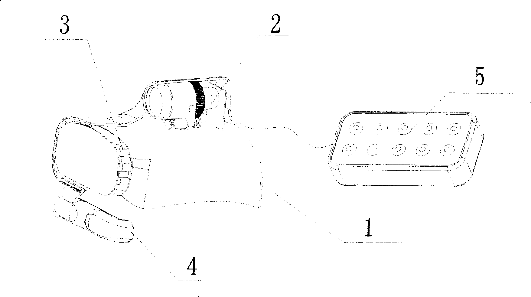
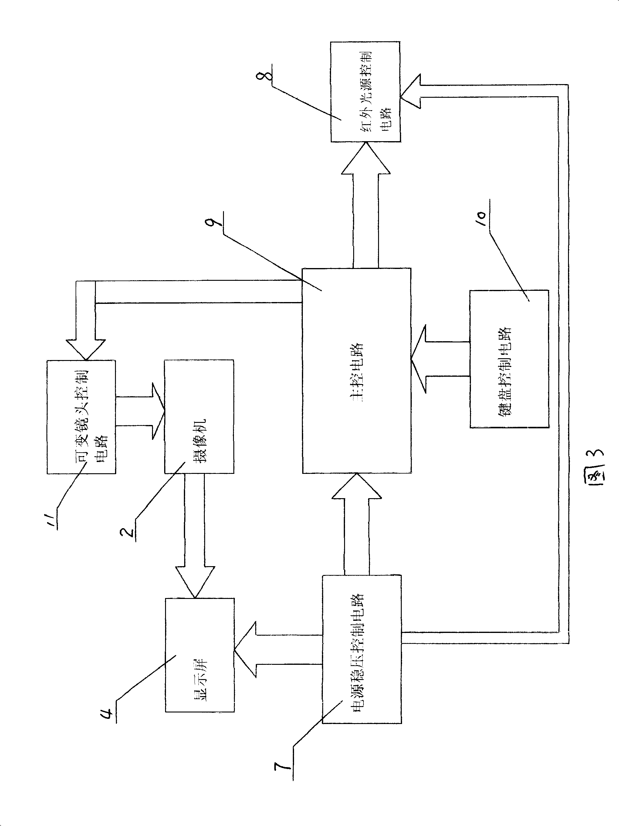
[0019] Embodiment 1, a kind of head-mounted night vision system, refer to figure 1 , Fig. 3, Fig. 4, are that camera 2 is fixed on the top of helmet 1, and the front portion of helmet 1 is provided with infrared emitting device 3, and display screen 4 is fixed below infrared emitting device 3, and the control circuit in controller 5 controls camera 2. The infrared emitting device 3 and the display screen 4 transmit signals. The control circuit in the controller 5 is a power supply voltage stabilization control circuit 7 connected to the infrared light source control circuit 8, the main control circuit 9, and the display screen 4 respectively. The main control circuit 9 Connect with the keyboard control circuit 10, the infrared light source control circuit 8, and the variable lens control circuit 11, the infrared light source control circuit 8 controls the infrared transmitter 3, the variable lens control circuit 11 controls the variable lens action of the video camera 2, and th...

Embodiment 2

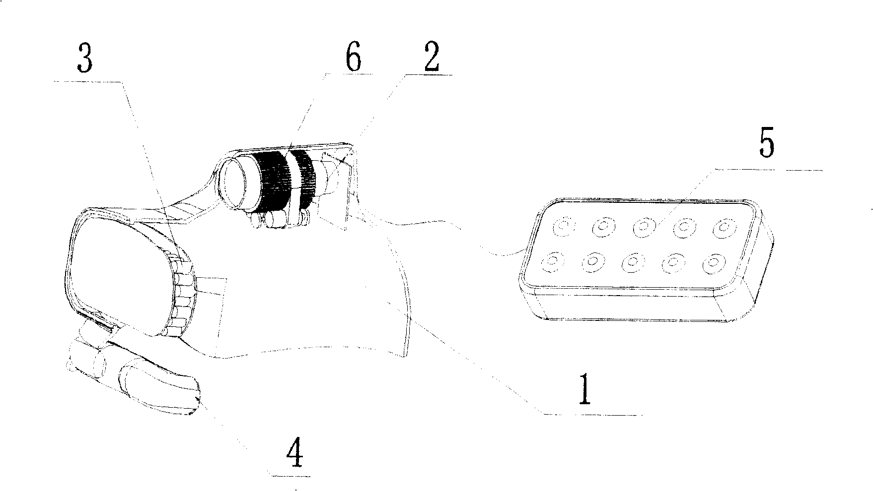
[0021] Embodiment 2, a kind of head-mounted night vision system, refer to figure 2 , Fig. 3, Fig. 4, are on the basis of embodiment 1, are provided with zoom lens 5 before video camera 2 lens, infrared ray emission device 3 is the matrix that is made up of infrared ray emission tube 6, and infrared ray emission device 3 is provided with protective screen , the others are exactly the same as in Example 1.

[0022] When using the present invention, the video signal processing of the high-definition low-illuminance black and white camera is input through J4-1 and output to the video transmitter through J3-1. All the way through J1-1 input to the micro-LCD display. When S7 "Focus+" is pressed, the positive 5V passes through R72, R28, R35, and one path passes through R18, R64 to control Q5 to turn on and Q4 to turn on the single-chip microcomputer U8-17 to detect the high-level button signal, and one path to enter U8- 19 detection. After U8-17 detects the high-level button sign...


PUM


Abstract

The night vision system is composed of headpiece, video camera and control circuit. The camera is fixed on up part of the headpiece. Infrared transmitting device is setup in front part of the headpiece. Display screen is fixed under the infrared transmitting device. Control circuit in the controller controls the camera, the infrared transmitting device, and display screen. The control circuit includes power supply voltage regulation control circuit connected to infrared source control circuit, main control circuit, and display screen respectively. The main control circuit is connected to the keyboard control circuit, the infrared source control circuit, and the zoom lens control circuit. The invention integrates image collection board, and infrared luminescence lamp board etc, providing features of small size, easy of use, low cost, sharp image and simple and convenient control.

Description

1. Technical field [0001] The invention belongs to the technical field of night vision equipment, in particular to a head-mounted night vision system. 2. Background technology [0002] In an environment without visible light, the brightness and clarity of the visible picture of the infrared night vision device are obviously much higher than that of the low-light night vision device. Infrared night vision devices are not limited by illumination, and can be observed in total darkness, and the effect is very good and the price is cheap. The low-light night vision device uses the low-brightness night sky light, star moonlight, atmospheric glow and other natural light reflected by the night target to enhance and amplify it, so as to achieve the purpose of reconnaissance suitable for the naked eye at night. It cannot work normally, and the production process of the low-light night vision device is particularly complicated, the cost is high, and the price is relatively high. 3. ...

Claims


Application Information

Patent Timeline
Patent Type & Authority Patents(China)
IPC IPC(8): G02B23/12G03B29/00G05B15/00G05B19/00G05F1/46
Inventor 王哲
Owner 王哲
Why Eureka
Try Eureka