Electricity saving device of full automatic three-phase motor

A three-phase motor, fully automatic technology, applied in the direction of adjusting electrical variables, AC motor control, instruments, etc., can solve problems such as incomplete use and semi-automation, and achieve the effect of reducing voltage and current

Inactive Publication Date: 2008-10-22
江门市盛航光电环保科技有限公司
View PDF7 Cites 0 Cited by
  • Summary
  • Abstract
  • Description
  • Claims
  • Application Information

AI Technical Summary

Problems solved by technology

However, the disadvantage of this power saver is that since the power saver uses the phase current detection circuit for current mutual inductance sampling, when the load of the motor connected to control changes, it needs to control the phase shift, and its operating point needs to be adjusted according to the size of the motor. It can only achieve semi-automatic effect, and the use is not perfect

Method used


Image

  • Electricity saving device of full automatic three-phase motor
  • Electricity saving device of full automatic three-phase motor

Examples


Embodiment Construction

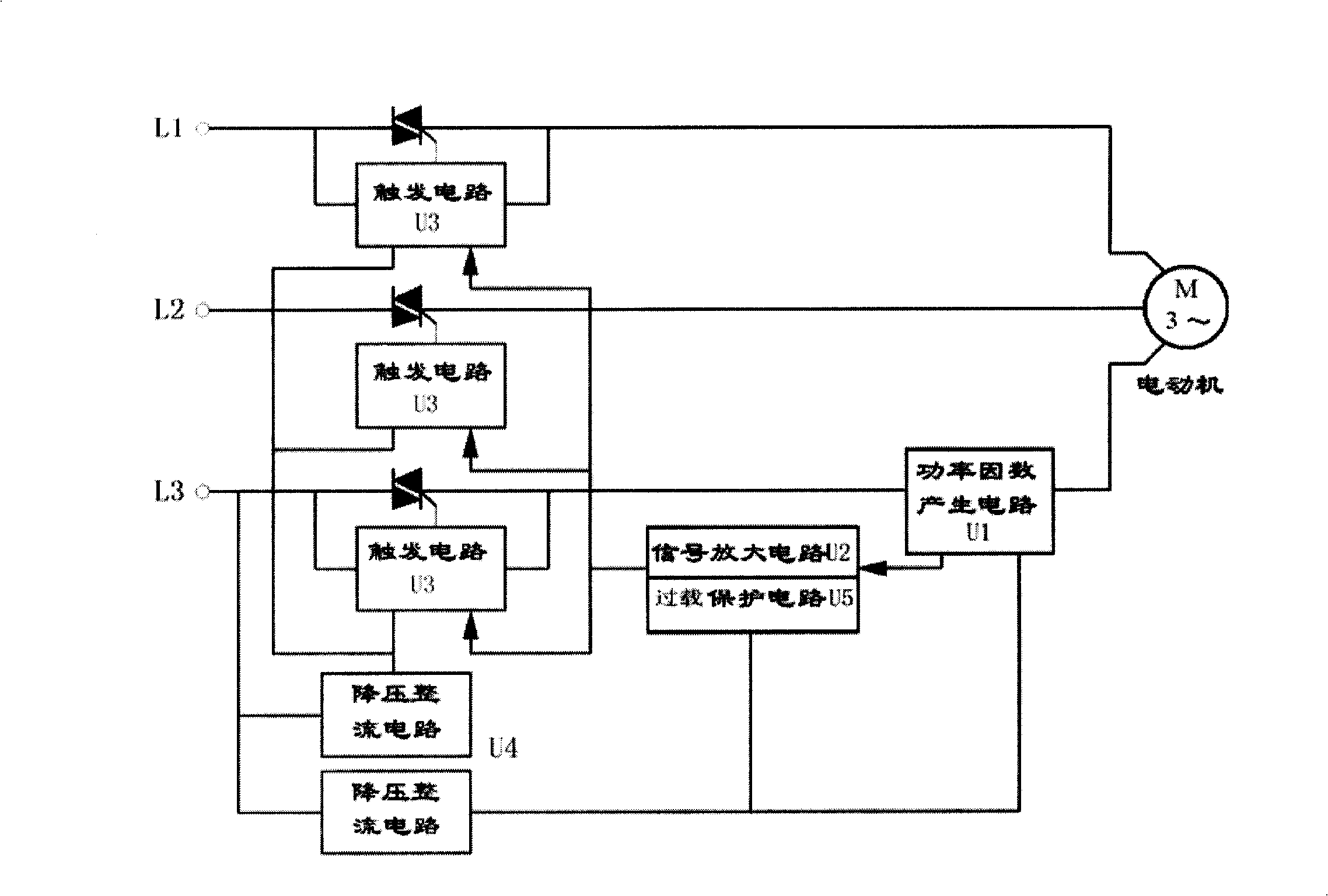
[0011] refer to figure 1 , fully automatic three-phase motor power saver, including power factor generating circuit U1, signal amplifying circuit U2, trigger circuit U3 and bridge rectifier circuit group U4, the input end of power factor generating circuit U1 is connected with three-phase power L1, L2, L3, The output end of the power factor generation circuit U1 is connected to the signal amplifier circuit U2, the output end of the signal amplifier circuit U2 is connected to the trigger circuit U3, the three-phase power L1, L2, L3 is connected to the three-phase motor after passing through the trigger circuit U3, and the bridge rectifier circuit group U4 They are respectively connected to the power input terminals of each circuit.

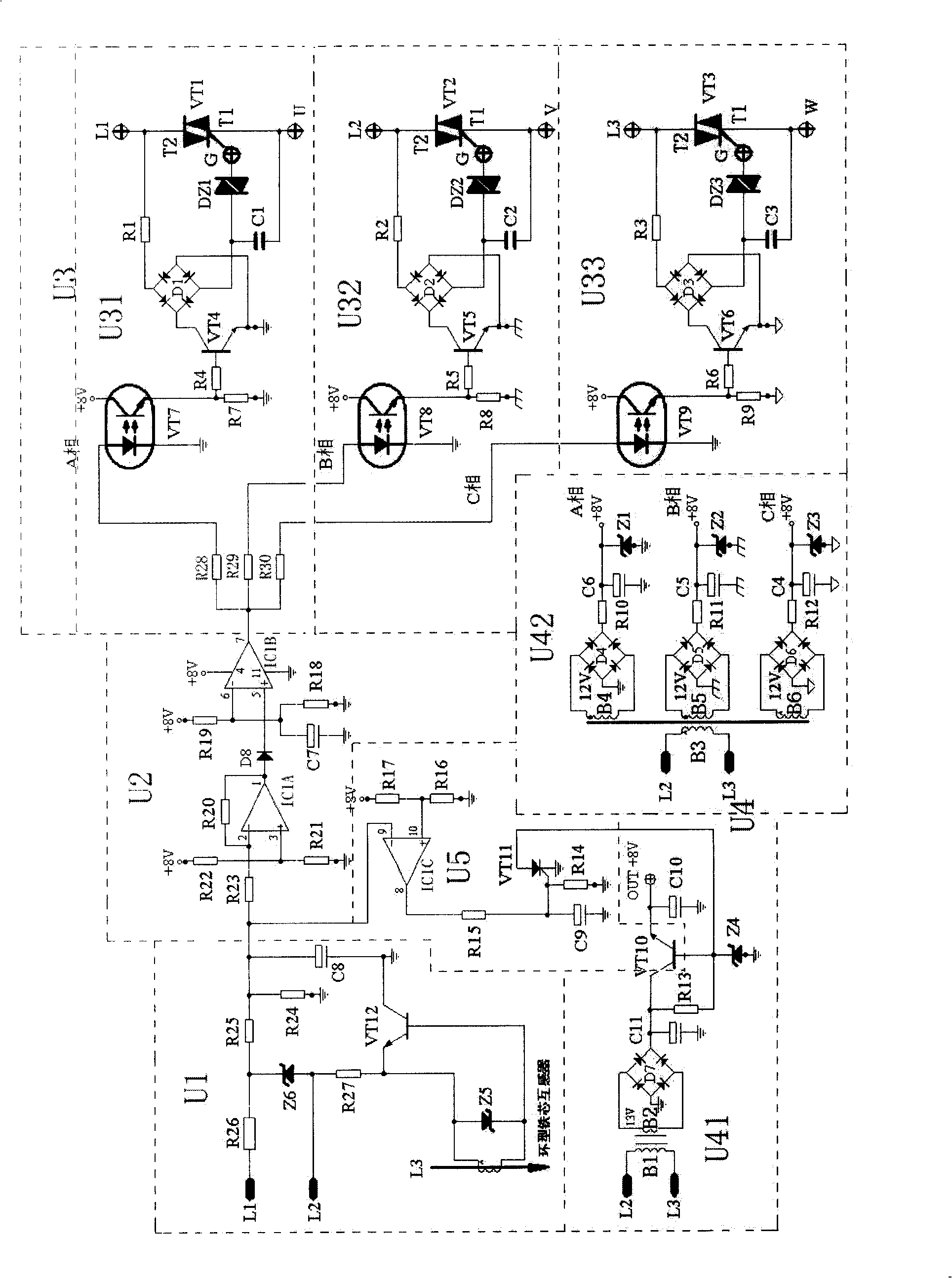
[0012] Refer below figure 2 The composition and principle of each resistor are described in detail.

[0013] (1) The power factor generation circuit U1 is used to detect the change of the power factor of the three-phase motor. It is a three-phas...


PUM


Abstract

It consists of the power factor generation circuit (PFG), the signal amplification circuit (SA), the trigger circuit (TR) and the bridge rectification circuit group (BRG). The input end of PFG connects to the 3- phase power supply. The output end of PFG connects to SA. The output end of SA connects to TR. The 3- phase power supply goes through TR and connects to the 3- phase motor. BRG connects with the power input ends of all circuits respectively. PFG, the signal amplification protection circuit and the controllable-silicon lead-angle regulation circuit (CLR) are adopted. CLR regulates the lead-angle of the controllable-silicon to raise or reduce the voltage applying on the motor to save electricity. The invention possesses features of simple structure, small volume, light weight, easy to install and obvious effect on saving electricity. It suits specially for the 3- phase motor with load change frequently or with intermissive work.

Description

technical field [0001] The invention relates to a power saver, in particular to a fully automatic three-phase motor power saver. Background technique [0002] In industrial and agricultural production, three-phase motors are widely used as power. At present, the motors selected by the mechanical equipment commonly used in factories are matched according to the maximum power required by the machinery. In actual use, the time of full load is very small, such as stamping machine tools, stretching equipment, injection molding machinery, etc., all work intermittently. Motors are often run under no-load or light-load conditions, resulting in wasted power. In order to solve this problem, people have thought of many ways, so a variety of power savers have emerged at the historic moment. Most of the current power savers use the motor to reduce the voltage when it is light-loaded to save electricity. One is to use the principle of changing the motor star-delta connection to achieve ...

Claims


Application Information

Patent Timeline
Patent Type & Authority Patents(China)
IPC IPC(8): H02P25/16G05F1/70
Inventor 陈景林李志成
Owner 江门市盛航光电环保科技有限公司
Why Eureka
Try Eureka