External set type ultrasonic fluid treatment device

A fluid processing and ultrasonic technology, applied in gas/liquid distribution and storage, pipeline systems, mechanical equipment, etc., can solve problems such as increasing fluid resistance, inability to install ultrasonic transducers inside pipelines, and unfavorable fluid transportation, etc. Achieve the effect of meeting the requirements of pipe wall strength

Active Publication Date: 2008-11-12
CHENGDU GUTE JIUZHOU TECH
View PDF8 Cites 0 Cited by
  • Summary
  • Abstract
  • Description
  • Claims
  • Application Information

AI Technical Summary

Problems solved by technology

For example, it can be seen from the accompanying drawings of the patent specification that in this product, the transducer is arranged in the concave pipe section of the outer wall of the pipe, and the inner wall of the pipe corresponding to the concave pipe section also protrudes toward the inside of the pipe. As a result, the inner diameter of the pipe will shrink, and the inner wall of the pipe will change in a staggered concave-convex shape, which will increase the fluid resistance and reduce the flow area, which is not conducive to the transportation of fluid.
[0004] After careful analysis, it is not difficult to find that for high-pressure pipelines with small diameters (below 300 mm), it is not suitable to install ultrasonic transducers inside the pipelines, and it is not easy to install ultrasonic transducers directly. set outside the pipe
This is because, in order to withstand higher liquid pressure, the pipe wall of the high-pressure pipe cannot be too thin, that is, the pipe wall of the high-pressure pipe is usually thicker. If the ultrasonic transducer is simply placed directly outside the pipe, the ultrasonic transducer will Most of the emitted energy will be reflected back by the thicker pipe wall, thus affecting the processing efficiency of ultrasonic waves
From this point of view, the technical solution disclosed in the above-mentioned Chinese Utility Model No. 00214308.9 cannot be directly applied to high-pressure pipelines
[0005] Therefore, for a high-pressure pipeline with a thicker wall, neither the ultrasonic transducer can be placed inside the pipeline, nor can the ultrasonic transducer be simply placed outside the thicker pipeline, thus forming a technical challenge

Method used


Image

  • External set type ultrasonic fluid treatment device
  • External set type ultrasonic fluid treatment device
  • External set type ultrasonic fluid treatment device

Examples


Embodiment 1

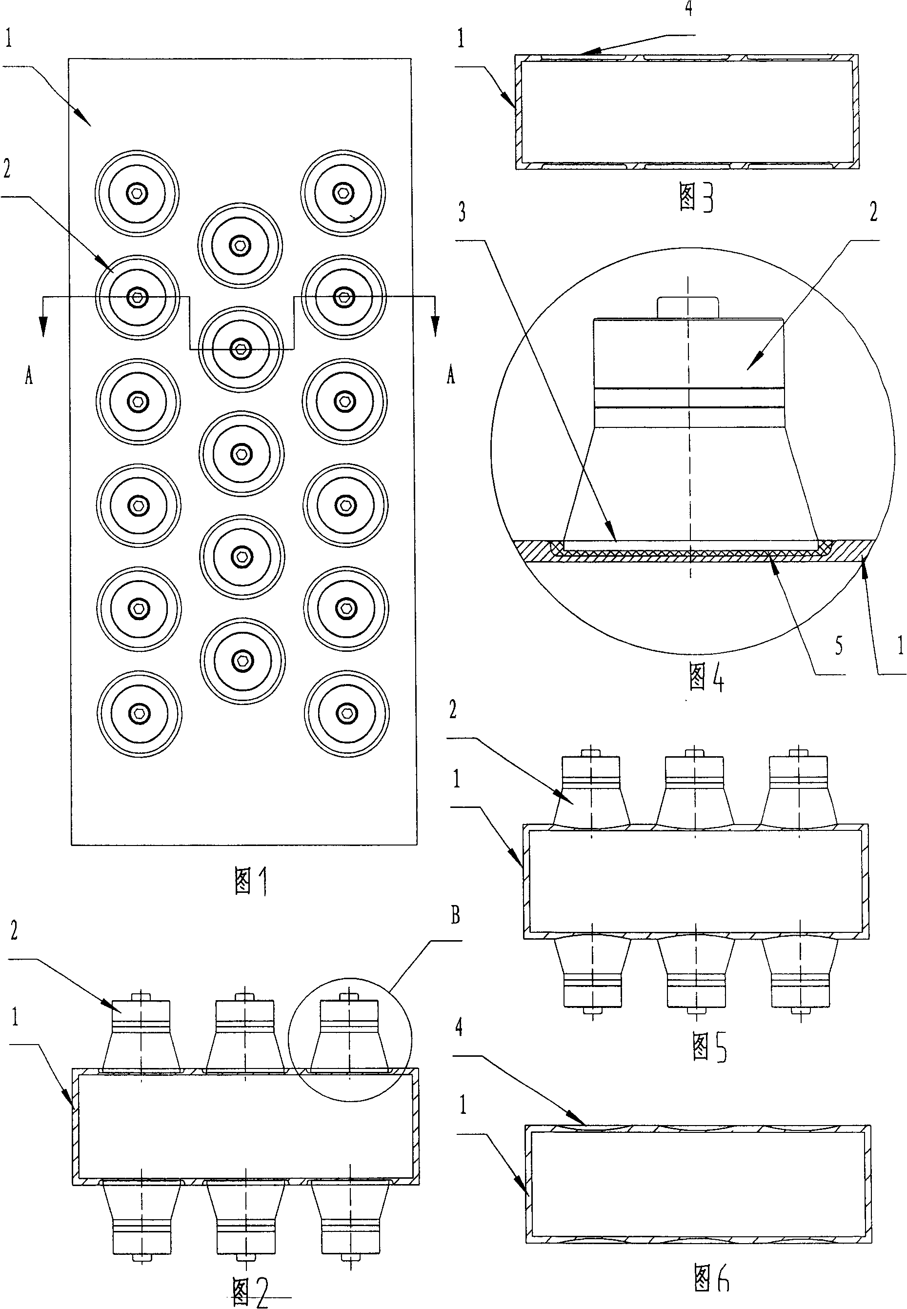
[0032] Embodiment 1: As shown in Figures 1 to 4, the ultrasonic fluid treatment device in this embodiment has an outer tube 1 and an ultrasonic transducer 2, the ultrasonic transducer 2 is arranged outside the outer tube 1, and the ultrasonic transducer The energy device has an ultrasonic transmitting end 3, and the ultrasonic transmitting direction of the ultrasonic transmitting end 3 is toward the inside of the outer tube 1, and is characterized in that an insertable cavity recessed toward the inner cavity of the outer tube is provided on the outer wall of the outer tube 1. The tube wall concave portion 4 of the ultrasonic transmitting end, the ultrasonic transmitting end 3 is inserted into the tube wall concave portion 4, and an adhesive is provided between the tube wall concave portion 4 and the ultrasonic transmitting end 3 Adhesive layer 5, the adhesive layer 5 bonds and fixes the tube wall concave portion 4 and the ultrasonic emitting end 3 as a whole, and makes the end ...

Embodiment 2

[0034] Embodiment 2: As shown in Figures 5 and 6, the ultrasonic fluid treatment device in this embodiment is similar to that in Embodiment 1, except that the shape of the outer tube 1 in this embodiment is slightly changed.

Embodiment 3

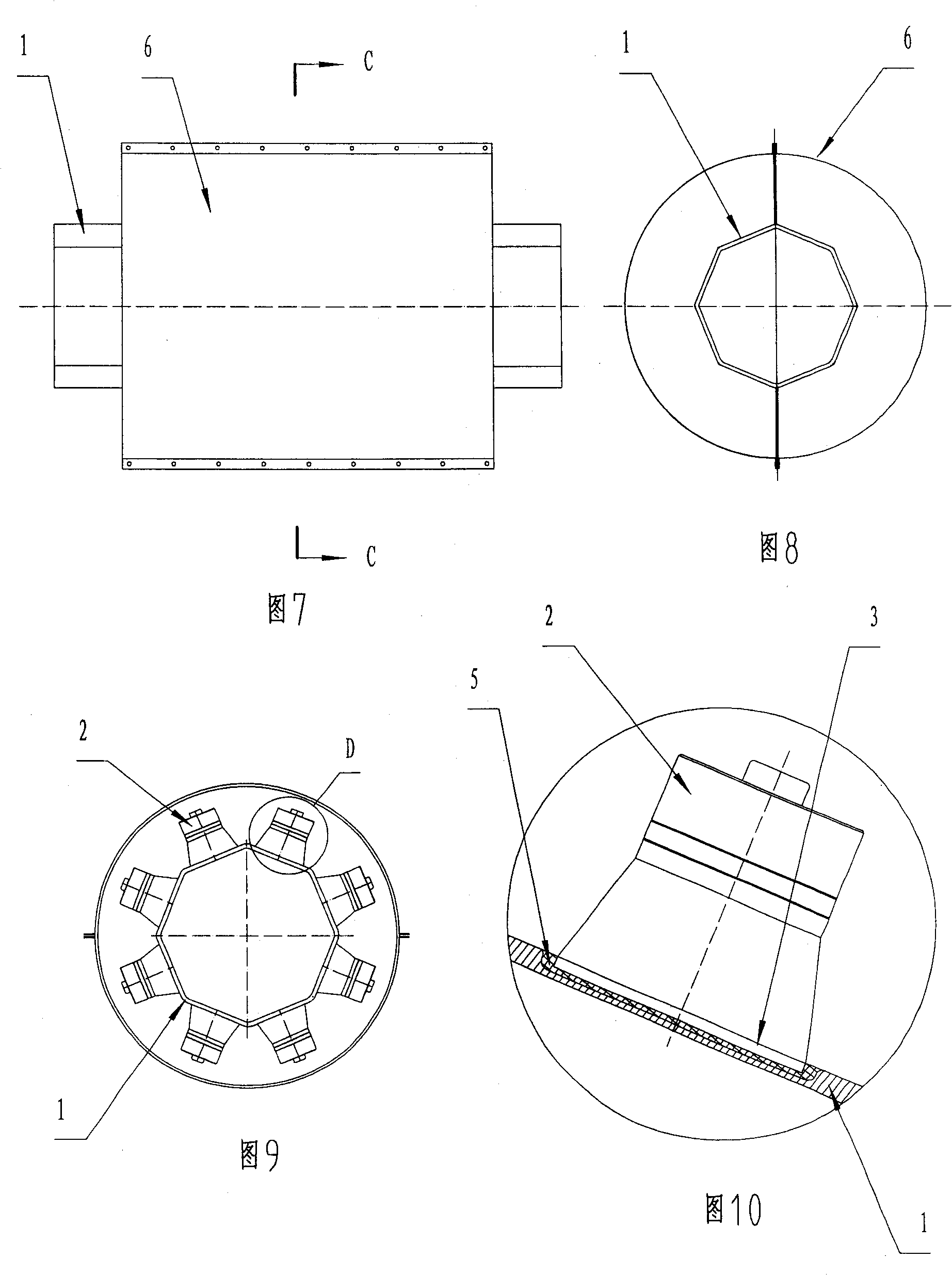
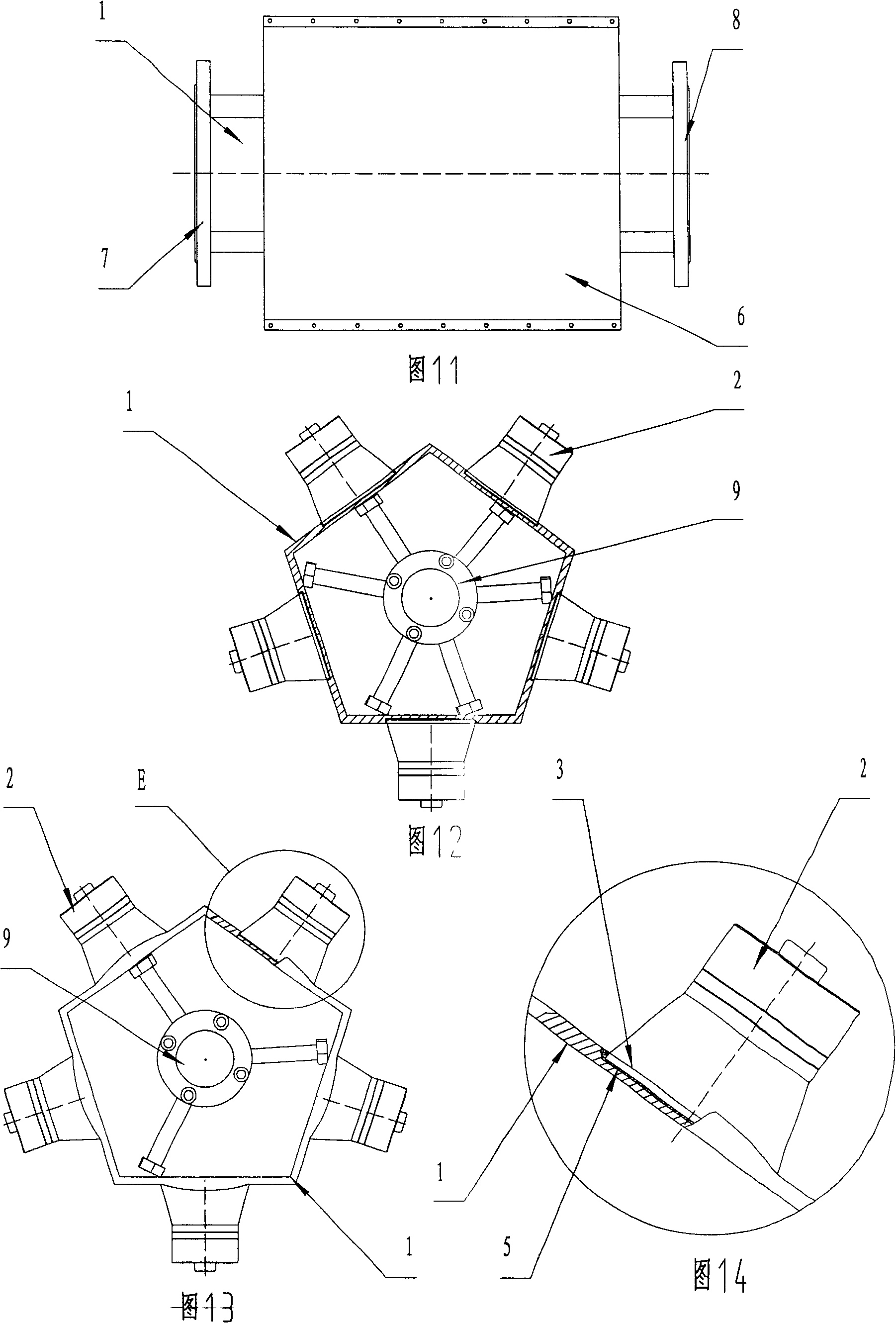
[0035] Embodiment 3: As shown in Figures 7-10, the ultrasonic fluid treatment device in this embodiment is similar to Embodiment 1, the difference is that in this embodiment, the shape of the inner cavity cross-section of the outer tube 1 is positive 8 polygon. In addition, the product of the first embodiment is provided with an outer cover 6, and the outer cover 6 completely covers the ultrasonic transducer 2 and the two ends of the outer tube 1 arranged outside the outer tube.


PUM


Abstract

An external ultrasonic fluid processing unit has an external tube and an ultrasonic transducer disposed outside the external tube. The ultrasonic transducer has an ultrasonic transmitting end, whose transmitting direction is towards the inside of the external tube. On outer wall of the external pipe is disposed a tube wall invagination capable of invaginating towards the direction of the external tube cavity and setting at the above ultrasonic transmitting end. Between the above tube wall invagination and the ultrasonic transmitting end there is a glue line, which is used for gluing the tube wall invagination and the ultrasonic transmitting end together.

Description

technical field [0001] The invention relates to an ultrasonic fluid treatment device applied to pipelines. Background technique [0002] In order to achieve the purpose of anti-scaling or fluid viscosity reduction, dispersion, cleaning, etc. in the pipeline, ultrasonic treatment technology is usually used now, that is, ultrasonic transducers are installed inside or outside the pipeline, and the energy emitted by ultrasonic waves is used to act on the inner wall of the pipeline or the fluid. , so as to avoid scaling on the inner wall of the pipeline or promote the flow of fluid. For example, the applicant discloses an ultrasonic anti-scaling device in Chinese Utility Model Patent No. 02244602.8, which is composed of an outer tube and an ultrasonic transducer, and a pipe connection structure is arranged at both ends of the outer tube. The ultrasonic transducer is fixed in the outer tube, the ultrasonic transducer has a transducer power connector extending out of the outer tub...

Claims


Application Information

Patent Timeline
Patent Type & Authority Patents(China)
IPC IPC(8): F17D1/16
Inventor 罗宪中
Owner CHENGDU GUTE JIUZHOU TECH
Why Eureka
Try Eureka