
Unit of transmission circuit for data wire of light display excited by electricity driven through electrical current

An electro-luminescence and transmission circuit technology, applied in static indicators, instruments, etc., to solve problems such as too many signal lines and poor picture quality

Inactive Publication Date: 2008-11-26
TPO DISPLAY
View PDF3 Cites 0 Cited by
  • Summary
  • Abstract
  • Description
  • Claims
  • Application Information

AI Technical Summary

Problems solved by technology

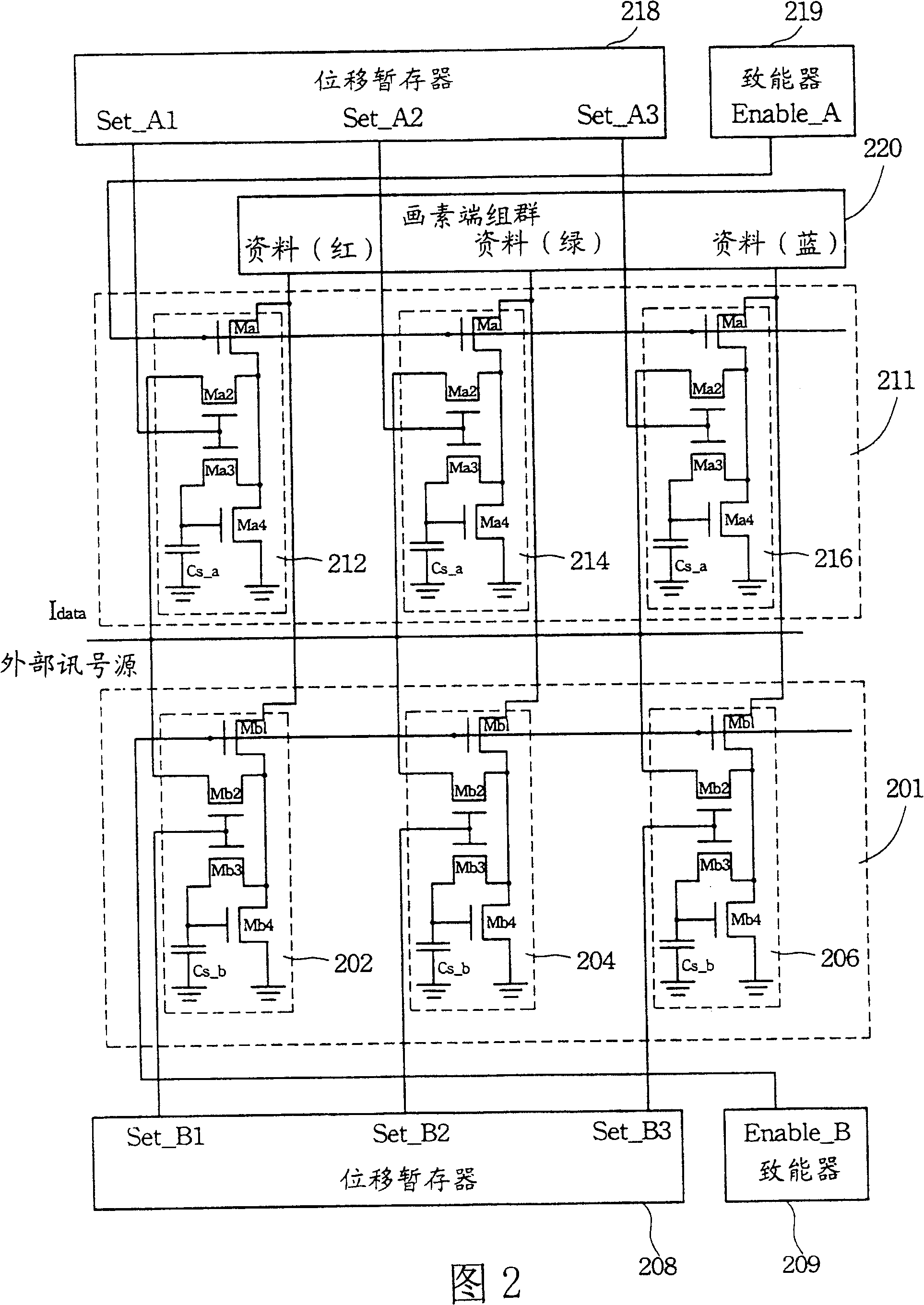
The structure of this current latch can greatly reduce the number of current sources, but since this structure is based on two circuit groups alternately, each circuit group and its shift register must be controlled by an external control signal line. Therefore, the number of external control signal lines used is too large, and the data current processed cannot be affected by two different circuit groups, resulting in poor image quality.

Method used


Image

  • Unit of transmission circuit for data wire of light display excited by electricity driven through electrical current
  • Unit of transmission circuit for data wire of light display excited by electricity driven through electrical current
  • Unit of transmission circuit for data wire of light display excited by electricity driven through electrical current

Examples


Embodiment Construction

[0055] In order to solve the problem of too many signal lines of the conventional current latch and the instability of tone, the present invention proposes a device for current-driven data line transmission circuit of an electroluminescence display.

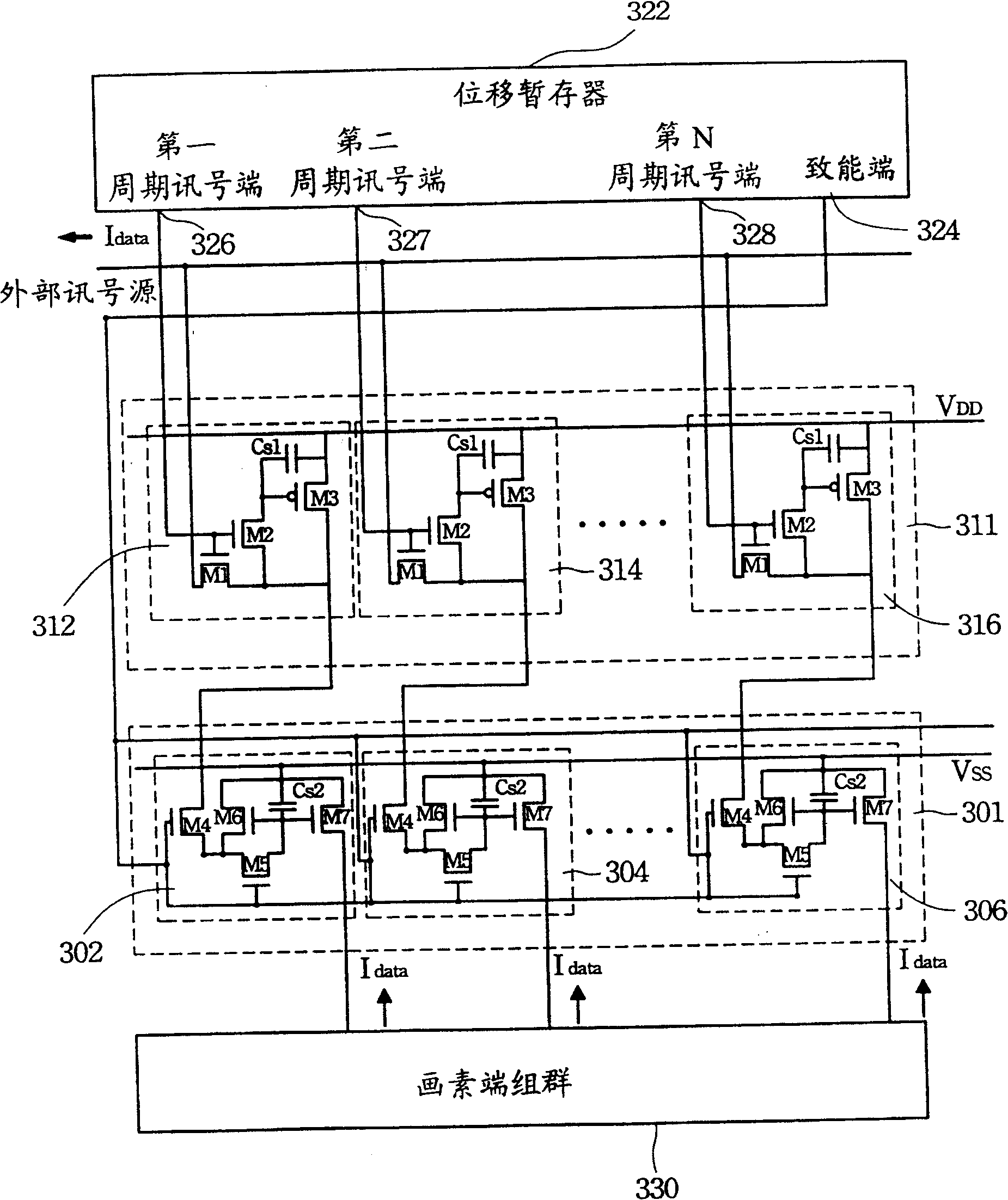
[0056] image 3 It is an embodiment of the present invention. image 3 In the circuit group 302 and the circuit group 312, seven thin film transistors (thin film transistor, TFT) M1-M7, two capacitors Cs1, Cs2 and a shift register 322 form a unit of current sink (current sink) type current latch circuit architecture. The capacitors Cs1 and Cs2 can store data current, and the shift register 322 can also have an enable function, which will be explained later. In the embodiment of the present invention, the two circuit groups inside the conventional current latch are changed from a structure in which data current is written and transmitted alternately in parallel to a structure in series.

[0057] exist image 3Among them, the s...


PUM


Abstract

The unit of transmission circuit is utilized to receive data current from external signal source and drive pixel group on screen excited by electricity. The unit includes first circuit group, second circuit group, and shift temporary storage. The shift temporary storage controls first circuit group to receive data current, and controls second circuit group to copy data from first circuit group and send data current to pixel group.

Description

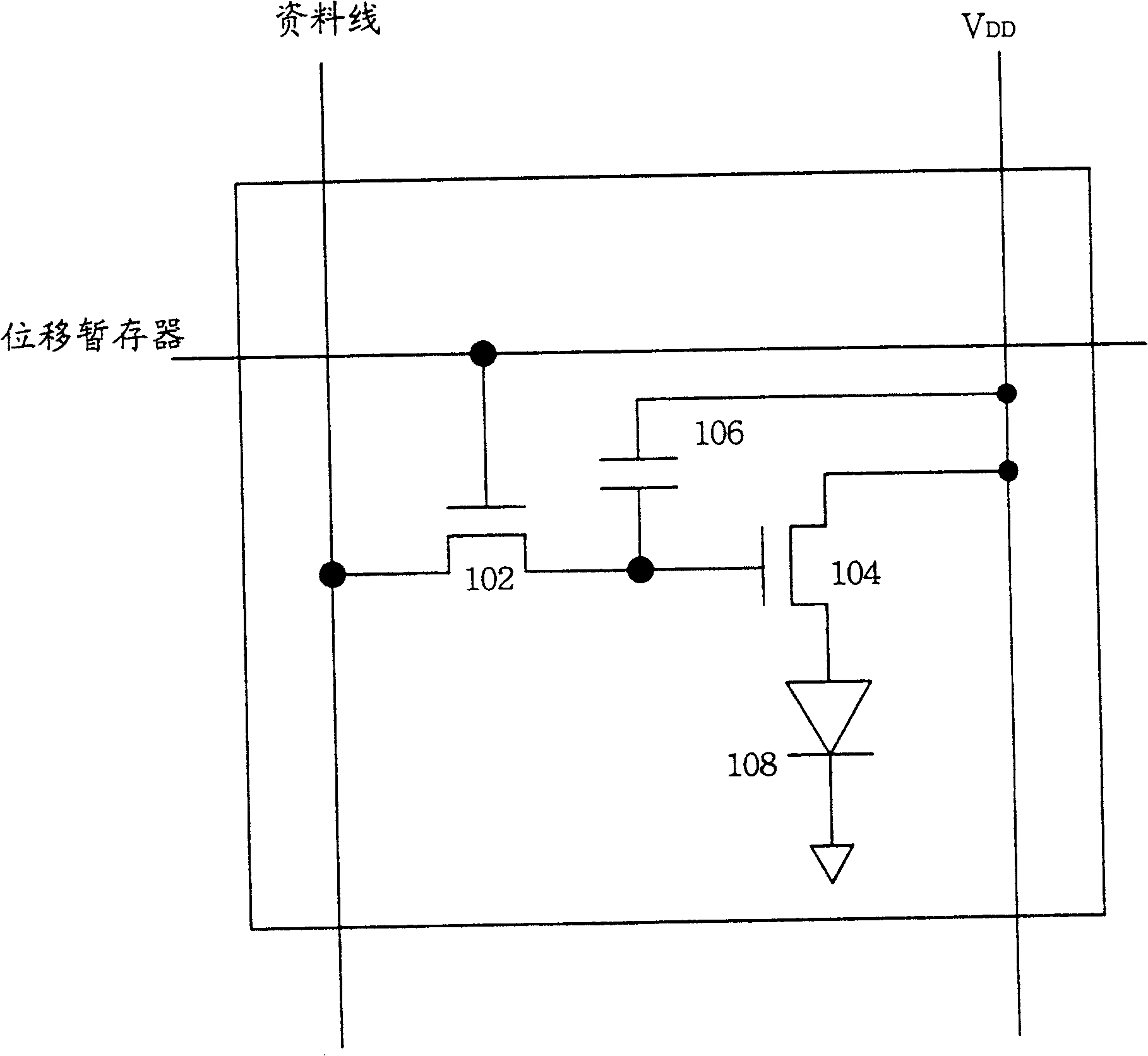
technical field [0001] The invention relates to a data line driving circuit, in particular to a device for current driving a data line transmission circuit of an electroluminescence display. Background technique [0002] Electroluminescence (EL) is a self-luminous display technology. Its operating principle is to inject carriers into semiconductor elements with luminescent properties through electrical means, and excite them to generate light. The electroluminescence can be simply divided into inorganic electroluminescence (inorganic electroluminescence) and organic electroluminescence (organic electroluminescence, OEL) according to the properties of the semiconductor elements used. One of the driving circuit architectures of the electroluminescence display is an active matrix circuit architecture. [0003] The simplest and most basic circuit configuration diagram of the active matrix is ​​as follows: figure 1 shown. exist figure 1 Among them, the function of the transis...

Claims


Application Information

Patent Timeline
IPC IPC(8): G09G3/30G09G3/00
Inventor 薛玮杰
Owner TPO DISPLAY
Learn More