Spring hydraulic operating mechanism for high voltage circuit breaker

A high-voltage circuit breaker and spring hydraulic technology, which is applied in the field of power transmission and transformation, can solve the problems of the energy storage piston and the energy storage cylinder being stuck together, the mechanism cannot store energy normally, and the energy storage piston cannot move. Reliable links and fewer parts

Active Publication Date: 2008-11-26
沈阳广驰工大高压电气有限公司
View PDF6 Cites 3 Cited by
  • Summary
  • Abstract
  • Description
  • Claims
  • Application Information

AI Technical Summary

Problems solved by technology

At present, the spring hydraulic operating mechanism used in high-voltage circuit breakers has three energy storage cylinders with a split structure. Due to the influence of the radial component force of the disc reed, the force is uneven, and the radial component force is likely to cause a single storage cylinder. The energy storage piston and the energy storage cylinder are locked together, so that the energy storage piston cannot move, and the sealing ring is easily damaged and leaks oil. If one energy storage cylinder fails to work, it will cause the disc reed group to be eccentrically stressed, so that the mechanism cannot store energy normally.

Method used


Image

  • Spring hydraulic operating mechanism for high voltage circuit breaker
  • Spring hydraulic operating mechanism for high voltage circuit breaker
  • Spring hydraulic operating mechanism for high voltage circuit breaker

Examples


Embodiment 1

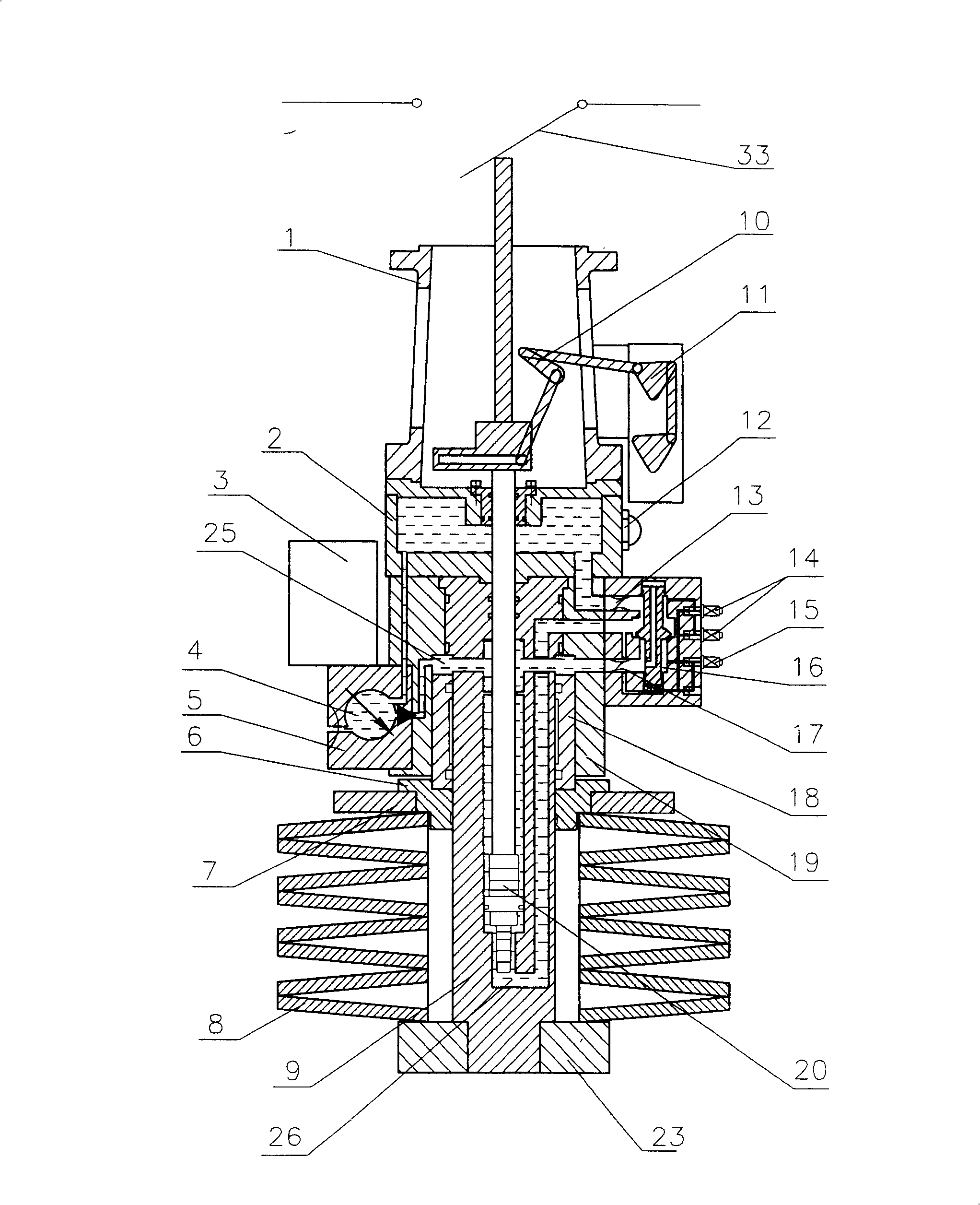
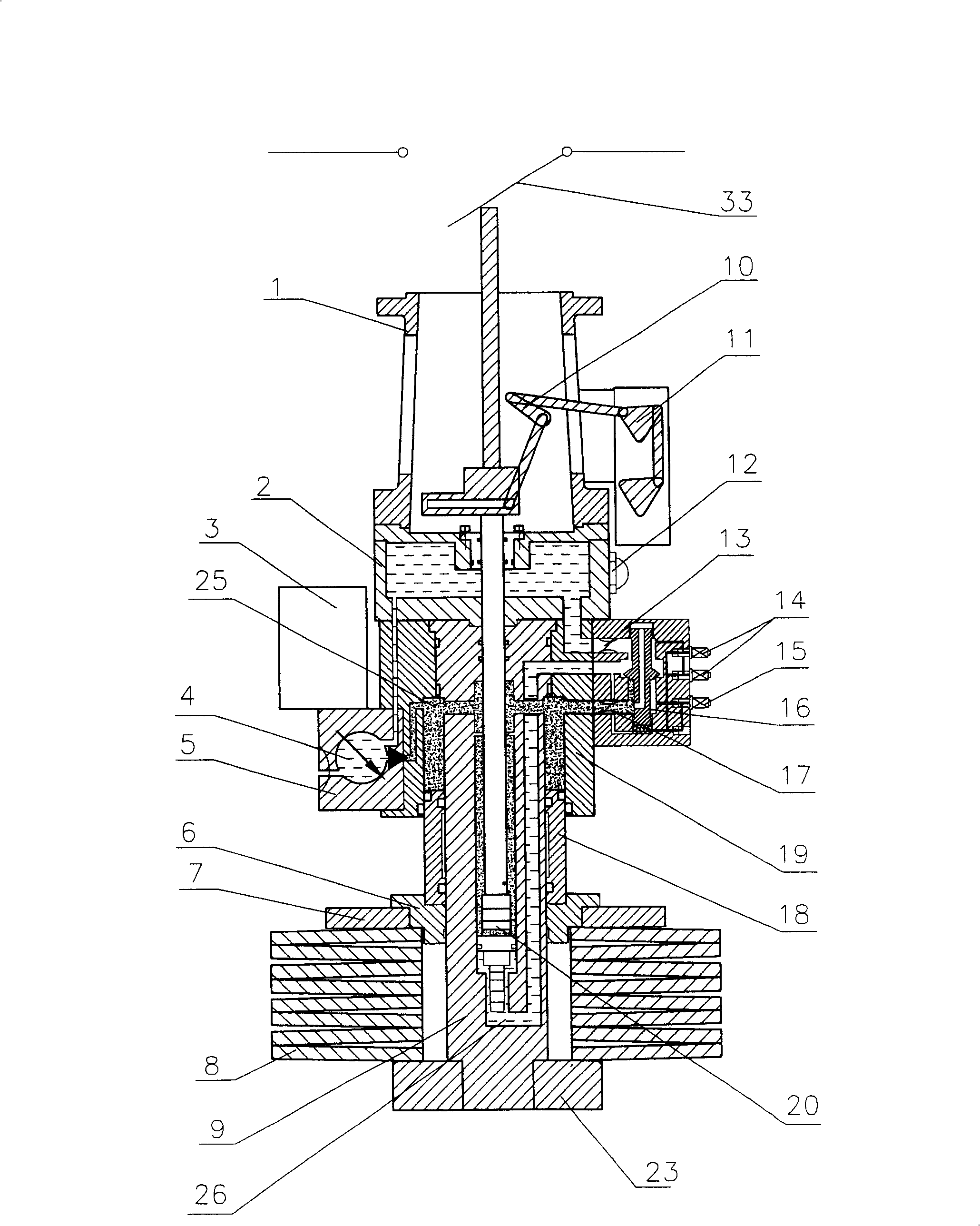
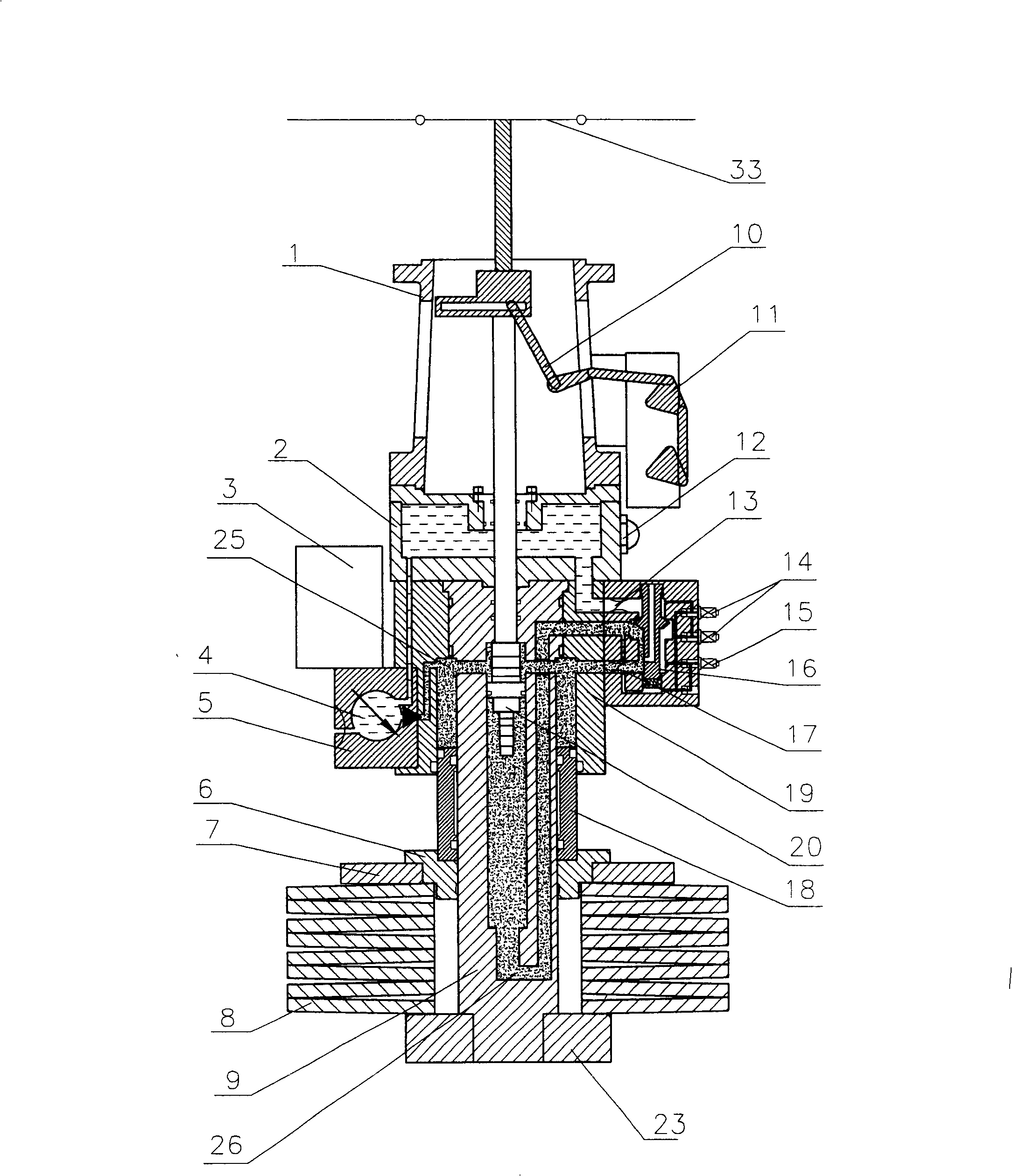
[0023] Embodiment 1: as figure 1 As shown, the mechanism pressure is released and it is in the opening position. The structure of the present invention includes a fuel tank 2, a motor 3, an oil pump 4, a disc reed group 8, a working cylinder 9, an energy storage piston 18, and a cylinder 19. The auxiliary switch 11 is fixed on the bracket 1, and one end of the working cylinder piston 20 passes through the The auxiliary switch connecting rod 10 is connected with the auxiliary switch 11, and the other end is placed inside the working cylinder 9, and the working cylinder 9 is placed in the hole of the cylinder 19. An oil tank 2 is fixed above the body 19 by bolts, an energy storage piston 18 is installed between the working cylinder body 9 and the cylinder body 19, and a pressure plate 6 is installed below the energy storage piston 18 on the working cylinder body 9. The φm end surface of the pressure plate 6 It is in contact with the end surface of the energy storage piston 18, ...

Embodiment 2

[0026] Embodiment 2: structure of the present invention is identical with embodiment 1, as figure 1 As shown, wherein the structure of the working cylinder 9 is as Figure 7 , Figure 8 Shown, the full length L of working cylinder body 9 1 540mm, the distance X between the end surface of the sealing groove I 27 opened between the outer diameter φa and φb near the end of φa and the end surface with the outer diameter of φa 1 30mm, the end with outer diameter φc has an external thread with diameter φg, the length L of external thread φg 3 is 80mm. The structure of cylinder block 19 is as Figure 5 , Image 6 As shown, in the sealing groove II 30 opened on the inner wall with the inner diameter of φc, the distance between the end surface near the end of the inner diameter φc and the end surface of the inner diameter φc is X 4 is 5mm. Energy storage piston 18 is a hollow cylinder, such as Figure 9 , Figure 10 As shown, its full length L 2 is 240mm, the minimum distance...

Embodiment 3

[0027] Embodiment 3: structure of the present invention is identical with embodiment 1, as figure 1 As shown, wherein the structure of the working cylinder 9 is as Figure 7 , Figure 8 Shown, the full length L of working cylinder body 9 1 540mm, the distance X between the end surface of the sealing groove I 27 opened between the outer diameter φa and φb near the end of φa and the end surface with the outer diameter of φa 1 54mm, the end with outer diameter φc has an external thread with diameter φg, the length L of external thread φg 3 100mm. The structure of cylinder block 19 is as Figure 5 , Image 6 As shown, in the sealing groove II 30 opened on the inner wall with the inner diameter of φc, the distance between the end surface near the end of the inner diameter φc and the end surface of the inner diameter φc is X 4 20mm. Energy storage piston 18 is a hollow cylinder, such as Figure 9 , Figure 10 As shown, its full length L 2 is 240mm, the minimum distance X b...


PUM


Abstract

This invention relates to a spring hydraulic operating unit used in a high voltage breaker including an oil tank, disk reed set, a working cylinder, an energy stored piston and a cylinder, in which, the working cylinder is set in the hole of the cylinder to be spaced by a circular truncated cone end face with the diameter of phia, an oil tank is fixed above the cylinder, the energy-stored piston is installed between the working cylinder and the cylinder to form a bush-like energy stored mode of the piston and the working cylinder, a press board is set under the energy stored piston on the working cylinder, the phim end face of the board is contacted with the end surface of the piston, the phin face is contacted with the disk reed set, a round plate is set outside of the phin cylinder of the press board, a plate is jacketed on the other end of the working cylinder, the disk reed set is sleeved between the press board and the plate and all sides of the cylinder is set with a reversing valve, an oil pump, a safety pressure releasing valve and a travel switch.

Description

technical field [0001] The invention belongs to the technical field of power transmission and transformation, and in particular relates to a spring hydraulic operating mechanism for a high-voltage circuit breaker. technical background [0002] The operating mechanism is the main equipment for high-voltage power transmission and transformation, and is an important part of the high-voltage circuit breaker. The opening and closing operations of the high-voltage circuit breaker are realized by the operating mechanism. At present, the spring hydraulic operating mechanism used in high-voltage circuit breakers has three energy storage cylinders with a split structure. Due to the influence of the radial component force of the disc reed, the force is uneven, and the radial component force is likely to cause a single storage cylinder. The energy storage piston is locked with the energy storage cylinder, so that the energy storage piston cannot move, and the sealing ring is easily dama...

Claims


Application Information

Patent Timeline
Patent Type & Authority Patents(China)
IPC IPC(8): H01H33/34H01H33/40
Inventor 富英李声周宇政
Owner 沈阳广驰工大高压电气有限公司
Why Eureka
Try Eureka