Fuel cell system and power generation method in fuel cell system

A fuel cell system and fuel cell technology, applied to fuel cell components, fuel cells, fuel cell additives, etc., can solve problems such as membrane damage and overall composition of the fuel cell system

Inactive Publication Date: 2008-11-26
PANASONIC CORP
View PDF3 Cites 0 Cited by
  • Summary
  • Abstract
  • Description
  • Claims
  • Application Information

AI Technical Summary

Problems solved by technology

[0011] In such a method of supplying fuel to the membrane electrode assembly with pipes, there is a problem that the piping for fuel supply and circulation and its transportation equipment are very large, and the overall structure of the fuel cell system is enlarged.
However, in such a case, the increase or decrease of the methanol aqueous solution contained in the first fuel container 555 is more likely to be affected by the exposure of the immersed membrane electrode assembly 553 from the liquid surface, and the above-mentioned problem of membrane damage will be more prominent.

Method used


Image

  • Fuel cell system and power generation method in fuel cell system
  • Fuel cell system and power generation method in fuel cell system
  • Fuel cell system and power generation method in fuel cell system

Examples


no. 1 Embodiment approach

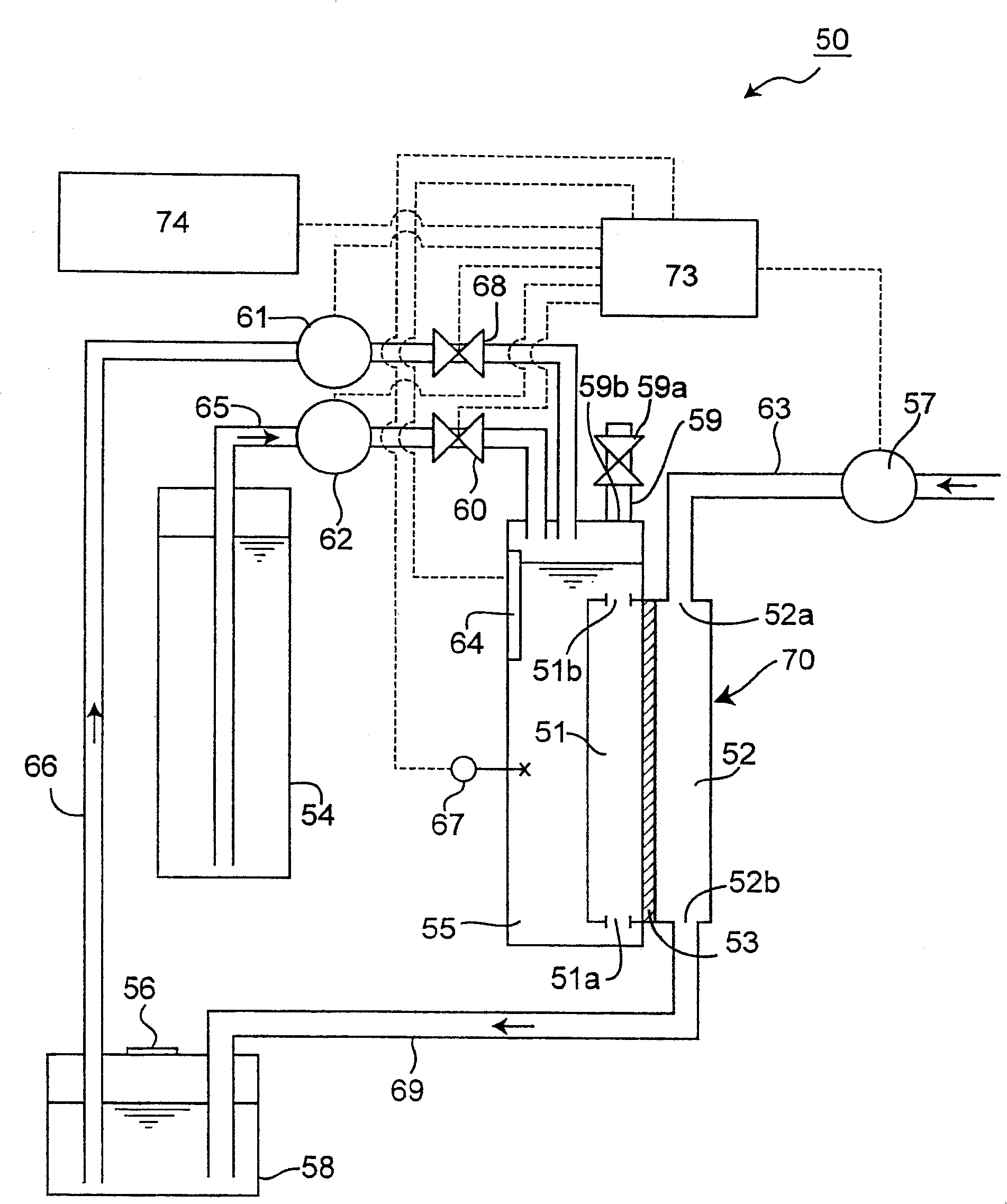
[0049] figure 1 A schematic configuration diagram showing a fuel cell system 50 according to the first embodiment of the present invention.

[0050] Such as figure 1 As shown, the fuel cell system 50 includes: a fuel cell main body 70, which is a power generation unit, and converts the chemical energy of the fuel into electrical energy in an electrochemical form to generate electricity; an auxiliary equipment system supplies the fuel cell main body 70 with the power required for the power generation. Fuel and the like perform auxiliary actions for power generation. In addition, this fuel cell system 50 is a direct methanol fuel cell (DMFC), which uses methanol aqueous solution as an example of an organic liquid fuel as fuel, and generates power by directly extracting protons from the methanol.

[0051] Such as figure 1 As shown, the fuel cell body 70 includes: an anode (fuel electrode) 51 , a cathode (air electrode) 52 , and a membrane electrode assembly 53 . The anode 51 ...

no. 2 Embodiment approach

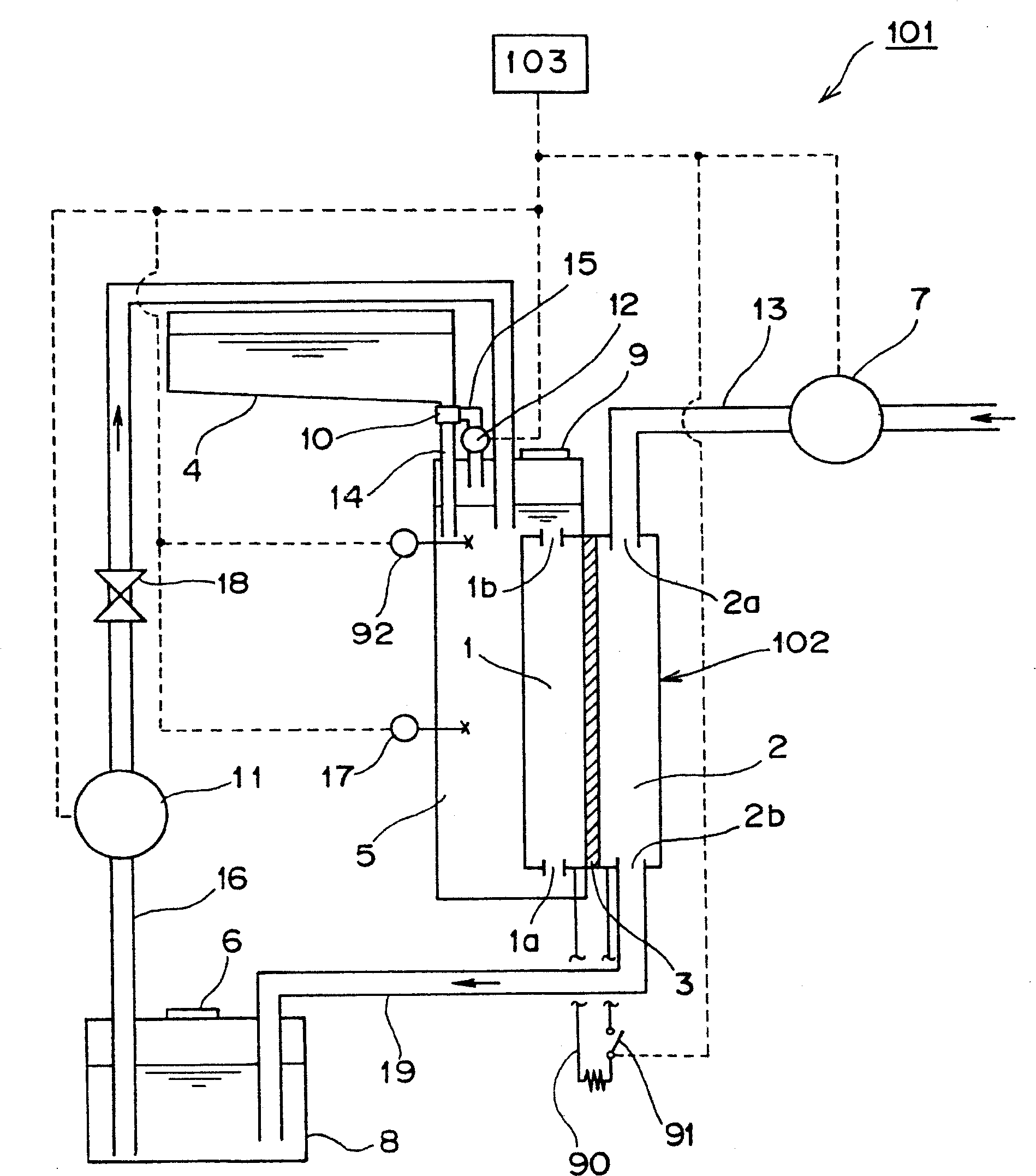
[0123] In addition, the present invention is not limited to the above-described embodiments, and may be implemented in other various forms. For example, the model configuration of the fuel cell system 101 according to the second embodiment of the present invention is as follows image 3 shown. Furthermore, the fuel cell system 101 of the second embodiment is different from the fuel system 50 of the first embodiment above in that it replenishes the liquid fuel in the intermediate tank that has been reduced during power generation stoppage without using a secondary battery for power supply. Although it has a different configuration, the configuration of the power generation part of the fuel cell main body (including the configuration of the auxiliary equipment system) is substantially the same as that of the first embodiment described above. Therefore, in the following description, the description will focus on this different configuration.

[0124] Such as image 3 As shown,...

no. 3 Embodiment approach

[0160] Figure 4 A schematic configuration diagram showing a schematic configuration of a fuel cell system 201 according to the third embodiment of the present invention. Such as Figure 4 As shown, the basic configuration of the fuel cell system 201 is the same as that of the fuel cell system 101 of the second embodiment described above, but the configuration of auxiliary equipment for recovering water generated at the cathode and the configuration of water supply are different. The following description will focus on these different components.

[0161] Such as Figure 4 As shown, a fuel cell system 201 includes a fuel cell main body 202 including an anode 21 , a cathode 22 and a membrane electrode assembly 23 . In addition, a power generation circuit 290 and a circuit switch 291 are provided to connect the anode 21 and the cathode 22 through respective electrodes (not shown in the figure).

[0162] In addition, the fuel cell system 201 is provided with the same auxiliar...


PUM


Abstract

A fuel cell system has a controller in communication with a fuel detector for activating power supply if a detection result received from the fuel detector indicates that a level of the liquid fuel has not reached the top of an anode, and for preventing power generation in a fuel cell until the detection result indicates that the level of the liquid fuel has reached the top of the anode.

Description

technical field [0001] The present invention relates to a fuel cell system, comprising: a fuel cell main body, which has a membrane electrode assembly disposed between an anode and a cathode disposed opposite to the anode; and a fuel for generating electricity by the fuel cell main body Auxiliary equipment such as a supply system particularly relates to a fuel cell system and a method for generating electricity by the fuel cell main body while directly supplying an organic liquid fuel such as methanol to the anode. Background technique [0002] The spread of portable electronic devices such as mobile phones, portable information terminals, notebook personal computers, portable audio equipment, and portable video equipment is rapidly progressing. Conventionally, such portable electronic devices have been driven by primary batteries or secondary batteries. The secondary battery needs to be charged after a certain amount of electric energy is used up, therefore, a charging dev...

Claims


Application Information

Patent Timeline
Patent Type & Authority Patents(China)
IPC IPC(8): H01M8/02H01M8/00H01M8/04H01M8/10
CPCH01M8/04619H01M8/04388H01M8/04201H01M8/04604H01M8/04223H01M8/04955Y02E60/523H01M8/04753H01M8/1011H01M8/04186H01M8/04225H01M8/04228H01M8/043H01M8/04302H01M8/04303Y02E60/50
Inventor 长谷川贤治青山俊之东阴地贤下田代雅文小野雅行堀贤哉小田桐优
Owner PANASONIC CORP
Why Eureka
Try Eureka