Planetary gear

A technology for planetary gearboxes and gearboxes, applied in gear transmissions, gear lubrication/cooling, belts/chains/gears, etc., which can solve problems such as friction corrosion, oil mist not reaching the inner ring gear, lack of lubrication in thrust bearings, etc. To achieve the effect of preventing friction corrosion

Inactive Publication Date: 2008-12-10
ZF FRIEDRICHSHAFEN AG
View PDF4 Cites 0 Cited by
  • Summary
  • Abstract
  • Description
  • Claims
  • Application Information

AI Technical Summary

Problems solved by technology

But this is impossible for planetary gearboxes, because at high speeds due to the strong ventilation of the ring gear, the oil mist cannot reach the ring gear, that is, it cannot reach the sun gear all the way
Therefore lack of lubrication on the thrust bearing and also fretting corrosion

Method used


Image

  • Planetary gear

Examples


Embodiment Construction

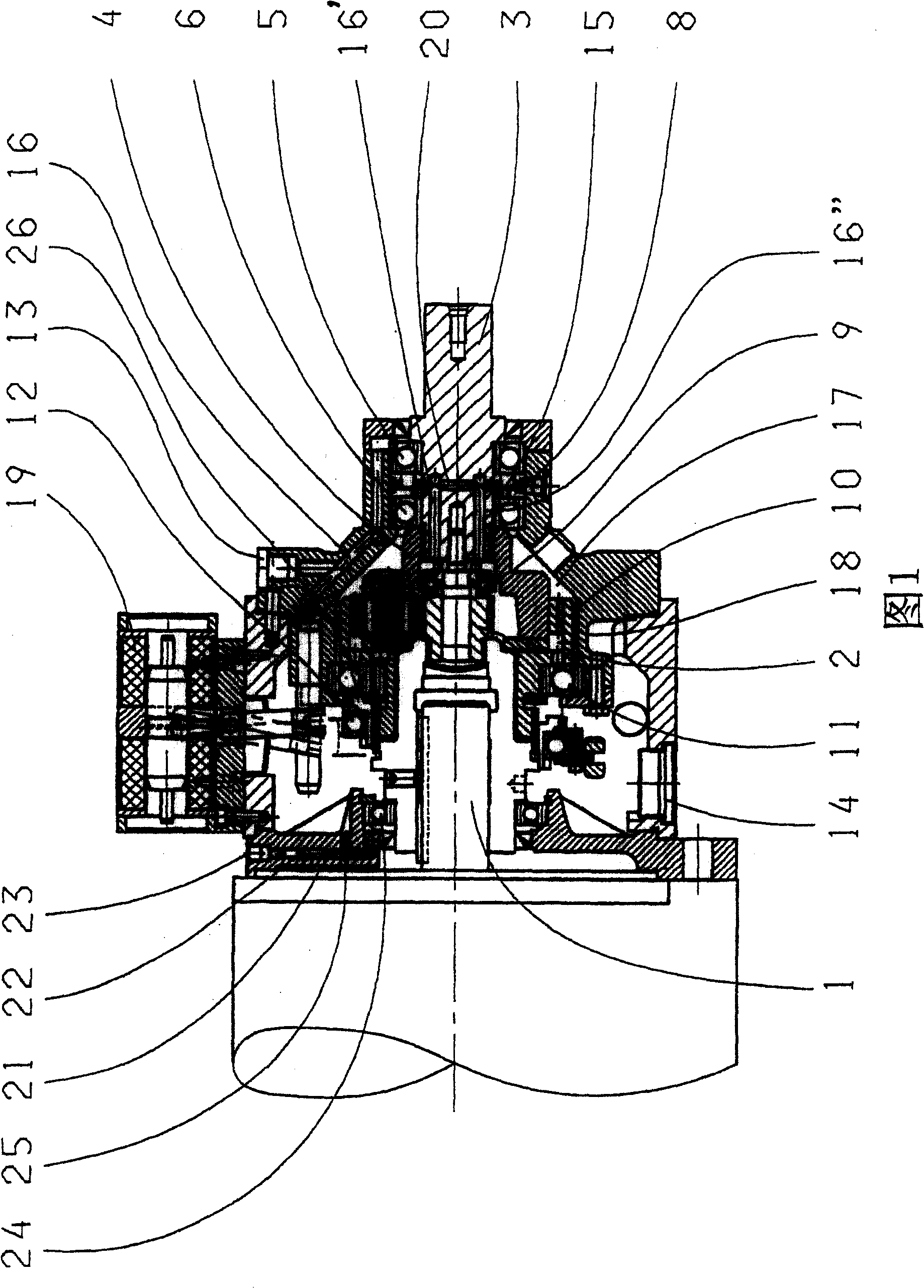
[0014] Since two-stage planetary gearboxes for machine tools are known to those skilled in the art, only the parts necessary for understanding the invention will be described below.

[0015] Use 1 to mark the transmission shaft 1 of the planetary gearbox, use 2 to mark the sun gear connected to it, use 3 to mark the driven shaft and use 4 to mark the planet carrier connected to it. 13 marks the oil inlet, which in the exemplary embodiment shown is located near the connection 19 of the sliding sleeve 26 in the bearing housing or in the gearbox housing. The oil inlet is connected to an oil pump not shown outside the gearbox and connected to the first outer bearing 5 of the driven shaft 3 through an oil pipe 16 formed on the casing wall of the gearbox. The first outer bearing 5 is separated from the second inner bearing 6 by a piston ring 8 , wherein the piston ring 8 has channels. The channel can either be a small hole 15 formed parallel to the axis of the driven shaft through ...


PUM


Abstract

The lubrication system for the planetary gear drive mechanism has an oil inlet (13), connected to an external oil pump in a fixed housing. Oil flows through a channel (16) supplying oil to outer (5) and inner (6) ball bearings for the output shaft (3). Oil flows through further channels to an axial thrust bearing (9) and planet-gear bearings and ring-gear bearings (11). Oil flows into the interior space (17) of the housing and leaves via a drain connection (14) in the housing wall (18).

Description

technical field [0001] The invention relates to a planetary gearbox having a transmission shaft connected to a sun gear, a driven shaft connected to a planet carrier and supported in a casing by a first outer bearing and a second inner bearing, wherein the two bearings are passed through a piston The rings are spaced apart from each other and also have a thrust bearing, a ring gear rotatably arranged in the gearbox housing via the ring gear bearing, an axially movable sliding sleeve and a lubrication circuit in the gearbox, which is used in particular for machine tool. Background technique [0002] These planetary gearboxes, which are mostly designed as single-stage or multi-stage planetary gearboxes, are mainly used in machine tool drives as well as in turning, milling and machining centres. The connectable planetary gearbox increases the power bandwidth of the spindle motor to increase the flexibility of the machine tool through high torques or high speeds when machining ...

Claims


Application Information

Patent Timeline
Patent Type & Authority Patents(China)
IPC IPC(8): F16H57/04F16H3/54
CPCF16H3/54F16H57/043F16H57/0471F16H57/0486
Inventor 哈拉尔德·埃克特
Owner ZF FRIEDRICHSHAFEN AG
Why Eureka
Try Eureka