Check patentability & draft patents in minutes with Patsnap Eureka AI!

Control system and data message transmission method in Ethernet

A control system and data message technology, applied in the field of network communication, can solve problems such as ineffective use of network topology resources, long spanning tree convergence time, and low service recovery efficiency

Active Publication Date: 2008-12-10
HUAWEI TECH CO LTD
View PDF3 Cites 0 Cited by
  • Summary
  • Abstract
  • Description
  • Claims
  • Application Information

AI Technical Summary

Problems solved by technology

[0010] 1. Since the traditional Ethernet system adopts connectionless technology, it cannot provide process engineering services, that is, it cannot provide reliable services that meet user requirements through optimized use of network resources according to user business needs and network resource conditions
[0011] 2. In order to prevent loopback, traditional Ethernet uses spanning tree to forward user data packets, and spanning tree is a pruned topology of a bridged network topology, so that some links in the bridged network are blocked, and network topology resources cannot be effectively used
[0012] 3. Since the existing Ethernet adopts the spanning tree protocol and generates the shared topology of the bridge network through distributed operations, there is still an election process for the determination of the root of the tree, so that the convergence time of the spanning tree is long. In this way, when the network Low business recovery efficiency in the event of a failure
This technology does not consider the bandwidth resource requirements of the end-to-end service data flow, but only considers the establishment of data forwarding tables based on the destination address. It cannot realize Ethernet traffic engineering based on network resource usage and service requirements.

Method used


Image

  • Control system and data message transmission method in Ethernet
  • Control system and data message transmission method in Ethernet
  • Control system and data message transmission method in Ethernet

Examples


Embodiment Construction

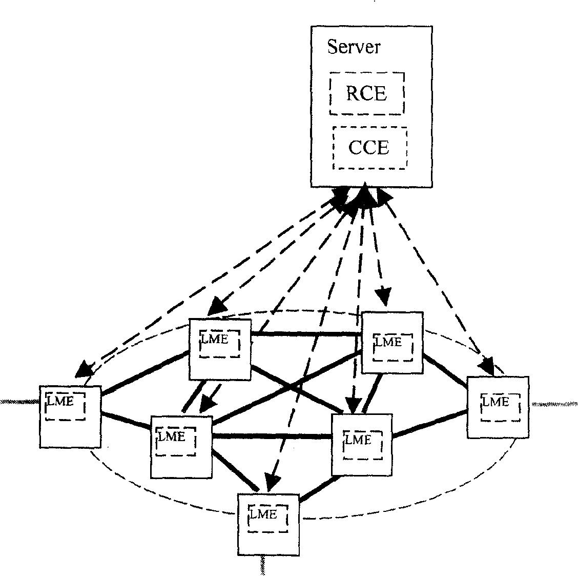
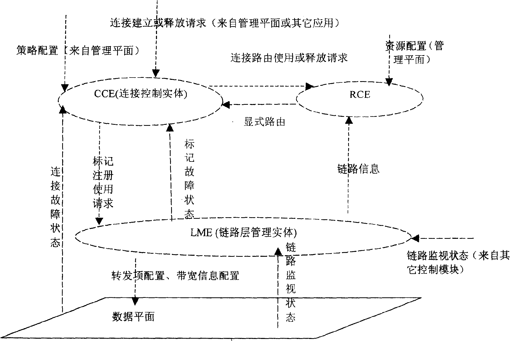
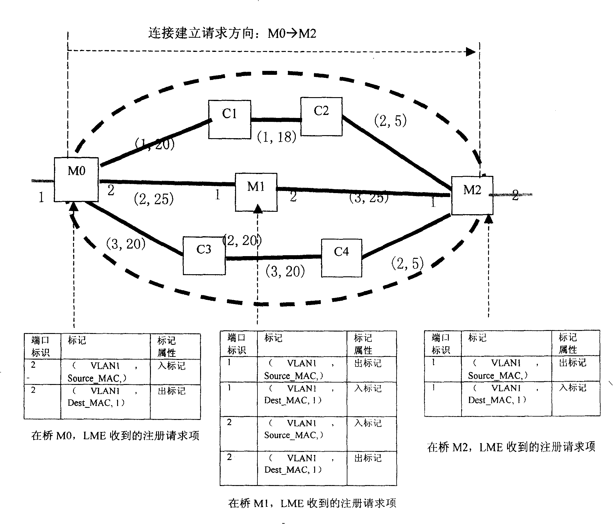
[0118] The technical solution of the present invention is aimed at a bridging network, that is, the present invention provides a control system for a bridging network in a single area. The present invention establishes a new bridging network by expanding the control system in the original traditional Ethernet control system, that is to say, the present invention establishes a new control plane for traditional Ethernet. The control system in the present invention expands the current traditional Ethernet two-layer control protocol such as LLDP, etc., and adopts a centralized control method of establishing and maintaining the network topology and centrally calculating the routes between the bridges connecting the endpoints, so that the control system can Pre-establish the forwarding path between the bridges connecting the endpoints for the data flow, thereby making the data flow in the Ethernet manageable, enabling the Ethernet to provide users with QoS guarantees, and enabling tr...


PUM


Abstract

A control system, a data message transmission method and a network device include: the control system obtains the link information in the Ethernet based on the layer 2 control protocol of the Ethernet, and establishes and maintains the network topology of the Ethernet based on the link information; the control system calculates the route connecting the endpoint network bridges for the connection establishment request received by itself based on the network topology, and configures the transmission path information of the data system of each network bridge passed by the connection; the data system of each network bridge transmits the data message based on the transmission path information. The implementation of the invention enables the data stream transferred in the Ethernet to be manageable and the data traffic in the Ethernet to be controllable. The implementation of the present invention needn't alter the encapsulation structure of the Ethernet data plane, and doesn't part from the Ethernet technology, but utilizes the traditional layer 2 control protocol of the Ethernet, thereby to make the Ethernet support the traffic engineering on the premise that the Ethernet is reconstructed at a low cost.

Description

technical field [0001] The invention relates to the technical field of network communication, in particular to a control system and a data message transmission method in the Ethernet. Background technique [0002] The Ethernet system consists of three subsystems, that is, the data forwarding system, the control system, and the management system. The data forwarding system is referred to as the data system. These three subsystems may also be called: data plane, control plane, and management plane. [0003] The data plane directly forwards and processes user data packets; the control plane does not directly process user data packets, but through control protocols such as STP / MRP / LLDP (Spanning Tree Protocol / Multiple Registration Protocol / Link Layer Discovery Protocol), etc. Obtain the network topology, provide configuration of relevant parameters and status for user data flow connection establishment, and provide reliability guarantee for it; the management plane is responsib...

Claims


Application Information

Patent Timeline
Patent Type & Authority Patents(China)
IPC IPC(8): H04L12/56
CPCH04L12/462H04L41/0803H04L41/12H04L41/344
Inventor 何健飞
Owner HUAWEI TECH CO LTD
Features
  • R&D
  • Intellectual Property
  • Life Sciences
  • Materials
  • Tech Scout
  • Unparalleled Data Quality
  • Higher Quality Content
  • 60% Fewer Hallucinations
Learn More