Vibration damper

An anti-vibration device and amplitude technology, applied in the direction of power plant, jet propulsion device, internal combustion propulsion device, etc., can solve the problems that the flow channel is long enough, cannot attenuate vibration, and it is difficult to adjust the flow channel length

Active Publication Date: 2009-01-07
BRIDGESTONE CORP +1
View PDF7 Cites 3 Cited by
  • Summary
  • Abstract
  • Description
  • Claims
  • Application Information

AI Technical Summary

Problems solved by technology

[0006] However, in the anti-vibration device of the above-mentioned Patent Document 1, if the internal volumes of the plurality of peripheral fluid chambers are to be sufficiently large, the thickness of the partition wall portion of the elastic body that divides these peripheral fluid chambers will become thinner, and it is difficult to make the inner volume of the plurality of peripheral fluid chambers sufficiently large. The flow path of the orifice on the bulkhead is long enough
Therefore, the anti-vibration device of Patent Document 1 has the problem that if the size of the device is enlarged, it is difficult to adjust the length of the flow path of the orifice communicating with the peripheral liquid chamber so that it is compatible with the vibration of a relatively low frequency (for example, 10 Hz or less). (Auxiliary vibration) Correspondingly, when the vibration input in the left-right direction or front-rear direction of the vehicle is a relatively low frequency, such vibration cannot be effectively damped and absorbed

Method used


Image

  • Vibration damper
  • Vibration damper
  • Vibration damper

Examples


no. 1 Embodiment approach

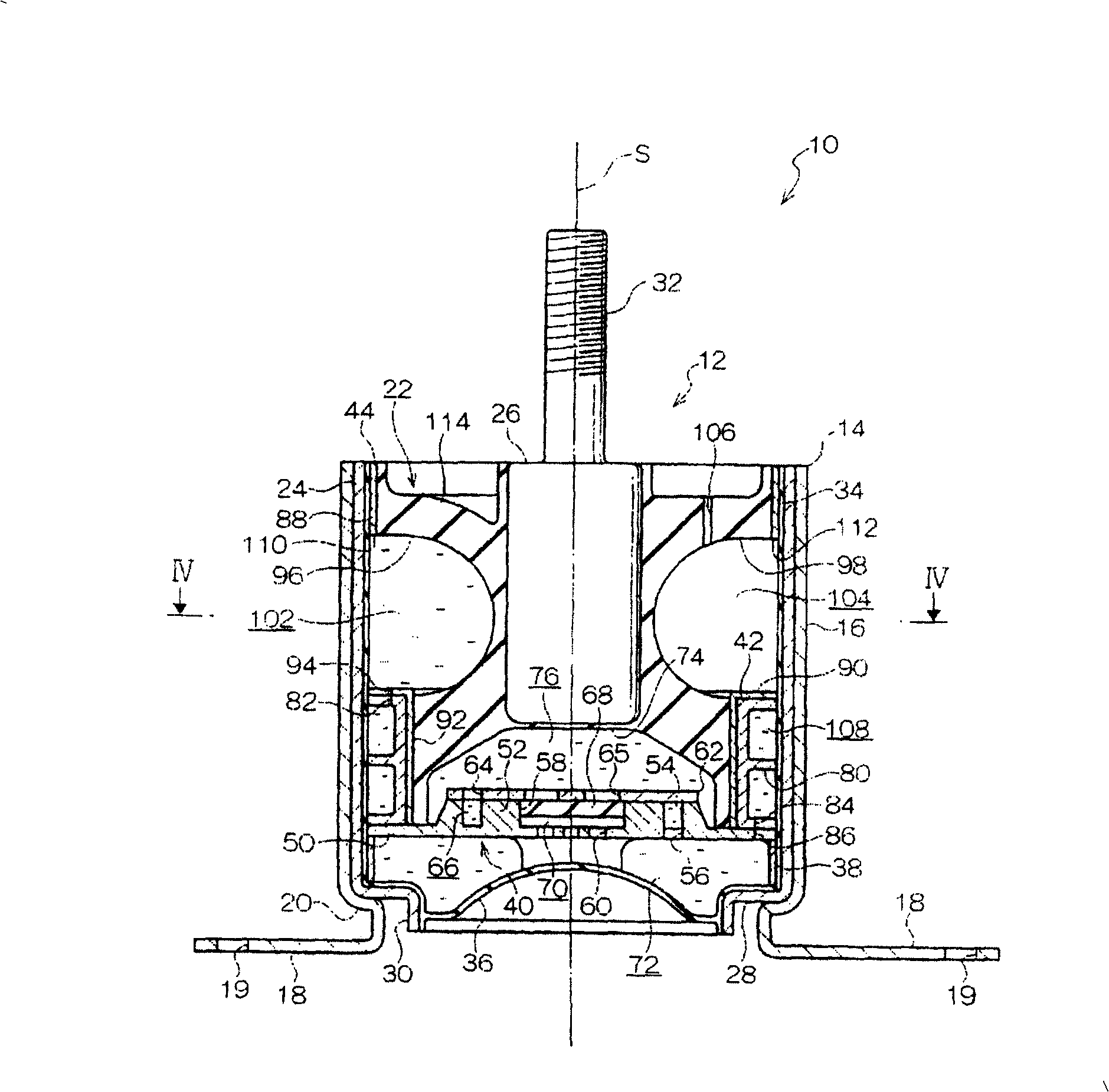
[0050] figure 1 The anti-vibration device of the first embodiment of the present invention is shown. This anti-vibration device 10 is used, for example, as an engine mount of an automobile, and supports an engine as a vibration generating unit on a vehicle body as a vibration receiving unit. In addition, the reference sign S represents the axis of the device, and the direction along the axis S is defined as the axial direction of the device, and the direction perpendicular to the axis S is defined as the radial direction of the device, which will be described below.

[0051] Such as figure 1 As shown, the anti-vibration device 10 has a device main body 12 formed in a substantially cylindrical shape and a bracket 14 for connecting and fixing the device main body 12 to the vehicle body side. A cylindrical holder portion 16 is formed on the bracket 14 , and a pair of leg portions 18 extending radially from the lower end portion of the holder portion 16 are integrally formed. M...

no. 2 Embodiment approach

[0086] Next, a vibration isolator according to a second embodiment of the present invention will be described.

[0087] Figure 5 A vibration isolator according to a second embodiment of the present invention is shown. This anti-vibration device 210 is used, for example, as an engine mount of an automobile, and supports an engine serving as a vibration generating unit on a vehicle body serving as a vibration receiving unit. In addition, the reference sign S represents the axis of the device, and the direction along the axis S is defined as the axial direction of the device, and the direction perpendicular to the axis S is defined as the radial direction of the device, which will be described below.

[0088] Such as Figure 5 As shown, the anti-vibration device 210 has a substantially cylindrical device main body 212 and a bracket 214 for connecting and fixing the device main body 212 to the vehicle body side. A cylindrical holder portion 216 is formed on the bracket 214 , a...

no. 3 Embodiment approach

[0125] A vibration isolator according to a third embodiment of the present invention will be described below.

[0126] Figure 9 and Figure 10 A vibration isolator according to a third embodiment of the present invention is shown. Furthermore, in the anti-vibration device 320 of the present embodiment, the structure and function are the same as those of the anti-vibration device 210 of the second embodiment (refer to Figure 5 ) are given the same reference numerals, and descriptions thereof will be omitted.

[0127] Such as Figure 9 As shown, like the anti-vibration device 210 of the second embodiment, a rubber elastic body 322 is provided on the anti-vibration device 210 between the intermediate cylinder 244 and the mounting part 226, and the upper end of the rubber elastic body 322 is integrally A partition wall portion 322A is formed to isolate one second pressure-receiving liquid chamber 302A from the outside of the device, and a partition wall portion 322B is integ...


PUM


Abstract

The present invention can effectively attenuate and absorb an auxiliary vibration even in the case that the auxiliary vibration input along a direction approximately orthogonal to a main vibration input along an axial direction of the apparatus, in addition that it is possible to effectively attenuate and absorb the main vibration while suppressing an engagement of a size of the apparatus. In a vibration proofing apparatus (210), two second pressure receiving liquid chambers (302A, 302B) are arranged between an outer tube (224) and a mounting attachment (226), and two second pressure receiving liquid chambers (302A, 302B) are communicated with an auxiliary liquid chamber (272) through two second orifices (308A, 308B). Accordingly, if an auxiliary vibration along an auxiliary amplitude direction orthogonal to an axial direction is input to the mounting attachment (226) from an engine side, a rubber elastic body (222) is elastically deformed along an auxiliary amplitude direction, and expands and contracts an internal volume of the second pressure receiving liquid chambers (302A, 302B), and the liquid circulates in the second pressure receiving liquid chambers (302A, 302B) and the auxiliary liquid chamber (72) with each other through the second orifices (308A, 308B). At this time, since a resonance phenomenon is generated in the liquid circulating between the second pressure receiving liquid chambers (302A, 302B) and the auxiliary liquid chamber (272) through the second orifices (308A, 308B) in synchronization with the input auxiliary vibration, it is possible to particularly effectively absorb a low-frequency vibration input along the auxiliary amplitude direction due to a pressure change, a viscous resistance and the like generated together with the resonance phenomenon of the liquid.

Description

technical field [0001] The present invention relates to a liquid-enclosed type anti-vibration device that absorbs vibration from a vibration-generating part such as an engine and prevents vibration from being transmitted to a vibration-receiving part such as a vehicle body, which is used as an engine mount on a general industrial machine or an automobile. Background technique [0002] For example, an anti-vibration device as an engine mount is arranged between the engine as the vibration generating part of the vehicle and the vehicle body as the vibration receiving part. The vibration isolating device absorbs the vibration generated by the engine and absorbs the vibration transmitted to the vehicle body Attenuation absorption. As such an anti-vibration device, there is known a liquid-enclosed type anti-vibration device in which an elastic body, a pressure-receiving liquid chamber, and a sub-liquid chamber are provided inside the device, and these liquid chambers communicate ...

Claims


Application Information

Patent Timeline
Patent Type & Authority Patents(China)
IPC IPC(8): F16F13/06B60K5/12F16F13/18
Inventor 小岛宏大坪义贵
Owner BRIDGESTONE CORP
Why Eureka
Try Eureka