Radiation cooling method for power device of refrigeration device

A heat dissipation cooling and refrigeration device technology, which is applied in the cooling of instruments, parts of instruments, cooling/ventilation/heating transformation, etc., can solve problems such as poor heat transfer effect, unit failure, small heat transfer temperature difference, etc., and achieve improvement Reliability and cost reduction effects

Inactive Publication Date: 2009-01-07
HANGZHOU DIANZI UNIV
View PDF4 Cites 0 Cited by
  • Summary
  • Abstract
  • Description
  • Claims
  • Application Information

AI Technical Summary

Problems solved by technology

In general, it is required that the surface temperature of the radiator installed with power devices such as intelligent power modules and rectifier bridges should be controlled below 65°C to ensure the reliability of the devices. It can be seen that the temperature difference between the two is only 15°C, the heat transfer temperature difference is small, and the heat dissipation and cooling effect not ideal
At the same time, it is installed in the air duct. Due to the limitation of the structure, the radiator is often in the eddy current area of ​​the gas, and the heat transfer effect is poor. Usually, the heat dissipation requirement can only be achieved by expanding the volume of the radiator.
In addition, due to the arrangement of radiators and some electric control boxes in the air duct, the heat dissipation effect of the condenser is also affected, which affects the performance of refrigeration devices such as air conditioners.
At the same time, because the radiator is in the air duct, the passing air will collect dust on the surface of the radiator, which will adversely affect the heat dissipation effect after a long time, and even cause the unit to malfunction.
If a small fan is used to dissipate heat, if it is not installed in the air duct, a set of air inlet and outlet channels must be designed, which will inevitably increase the complexity of the structural design; at the same time, due to the addition of a small fan, the reliability of the device will be relatively reduced

Method used


Image

  • Radiation cooling method for power device of refrigeration device
  • Radiation cooling method for power device of refrigeration device

Examples


Embodiment Construction

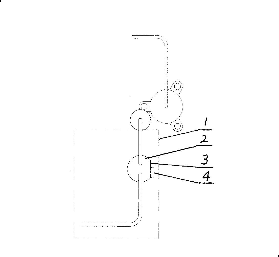
[0011] Such as figure 1 As shown, the gas-liquid separator 2 in the low-temperature suction circuit part 1 of the compressor (the dotted line box part in the figure) has a plane 3 as an installation surface, and the power device 4 that needs to be dissipated in the electric control box of the refrigeration device is installed on the on that plane. Through the low-temperature refrigerant circulation in the gas-liquid separator, the heat transfer on this plane reduces the temperature of the device and realizes heat dissipation and cooling.

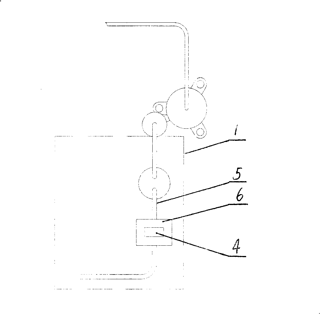
[0012] Such as figure 2 As shown, a metal heat-conducting installation surface 6 with good thermal conductivity is provided on the suction pipeline 5 in the low-temperature suction circuit part 1 of the compressor (the dotted line box part in the figure), and the metal heat-conducting mounting surface 6 with good thermal conductivity is arranged, and the cooling device electric control Power devices 4 are mounted on this face. Through th...


PUM


Abstract

This invention relates to a heat dissipation and cooling method for power parts of refrigerating apparatus, which adopts the means of direct conduction,by which the power parts in need of heat dissipation and cooling contact with the external surface of vapor-liquid separator or aspirator pipeline in the portion of compressor low-temperature aspiratory loop. It's available to directly contact the power parts in need of heat dissipation and cooling with the installed plane of vapor-liquid separator or aspirator pipeline. The invention can not only guarantees the demand of heat radiation and cooling for power parts of refrigerating apparatus, but also lowers the cost of hardwires for heat radiator system, furthermore, improves the reliability for the heat dissipation system.

Description

technical field [0001] The invention relates to a heat dissipation and cooling method, in particular to a heat dissipation and cooling method for power devices in a refrigeration device. Background technique [0002] Refrigeration devices such as inverter air conditioners generally have power devices such as intelligent power modules and rectifier bridges. The surface temperature of these devices is relatively high during operation, and cooling measures must be taken to dissipate heat, otherwise they cannot work normally. [0003] Existing heat dissipation and cooling methods for power devices mainly adopt conduction and convection. Generally, radiators and small fans for heat dissipation are installed on the surface of these devices that need heat dissipation, or radiators are installed in the heat exchanger air duct of the outdoor unit of the air conditioner. Cooling is by forced ventilation. These methods will make the structure of the electric control box relatively co...

Claims


Application Information

Patent Timeline
Patent Type & Authority Patents(China)
IPC IPC(8): H05K7/20G12B15/02
Inventor 丁强黄国辉王剑姜周曙
Owner HANGZHOU DIANZI UNIV
Why Eureka
Try Eureka