
Stabilivolt type pressure reducer

A pressure-reducing valve and voltage-stabilizing technology, applied in safety valves, balance valves, valve devices, etc., can solve the problems of hydrogen leakage, hydrogen leakage, explosion, etc., and achieve the effect of energy saving

Inactive Publication Date: 2009-01-21
刘敬善
View PDF5 Cites 0 Cited by
  • Summary
  • Abstract
  • Description
  • Claims
  • Application Information

AI Technical Summary

Problems solved by technology

[0002] At present, the structural form of the traditional pressure reducing valve is similar to the pressure stabilizing device of the present invention, and it is rarely used in the oil supply system of the generator shaft seal. The reason is that the system equipment is complicated and there are many pipelines. During use, it is easy to resonate with the system or get stuck, causing oil cut-off and causing serious accidents such as hydrogen run-off and hydrogen leakage.
The generator is full of hydrogen, once it leaks, it will cause a fire or even an explosion. The function of the shaft seal oil supply system is to establish a sealing oil pressure higher than a certain value of hydrogen at the shaft end of the generator to seal the hydrogen so that it will not leak. The traditional reduction Pressure valves are not used because they do not have such strict safety

Method used


Image

  • Stabilivolt type pressure reducer
  • Stabilivolt type pressure reducer
  • Stabilivolt type pressure reducer

Examples


Embodiment Construction

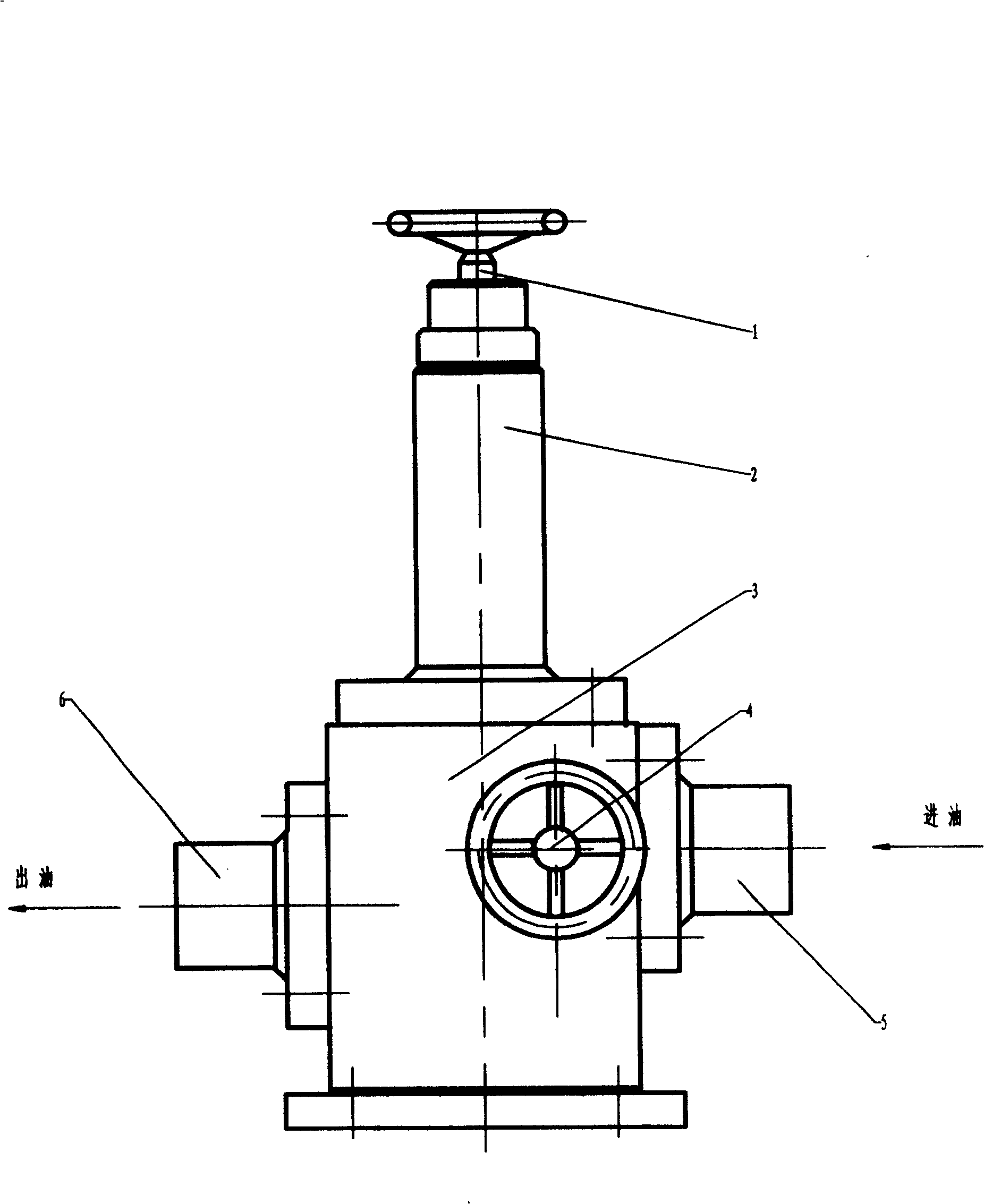
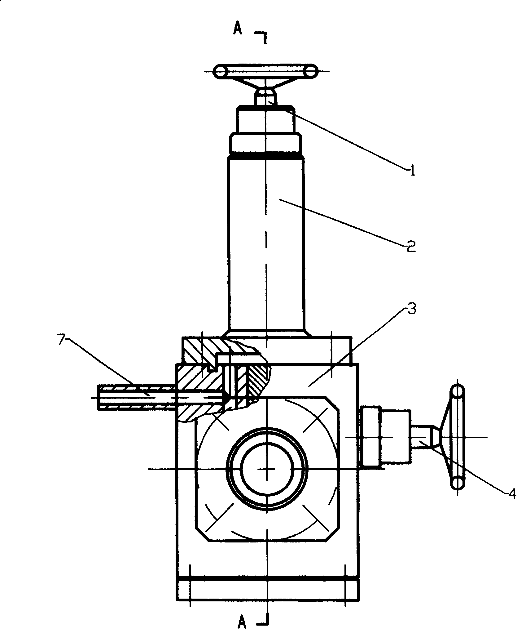
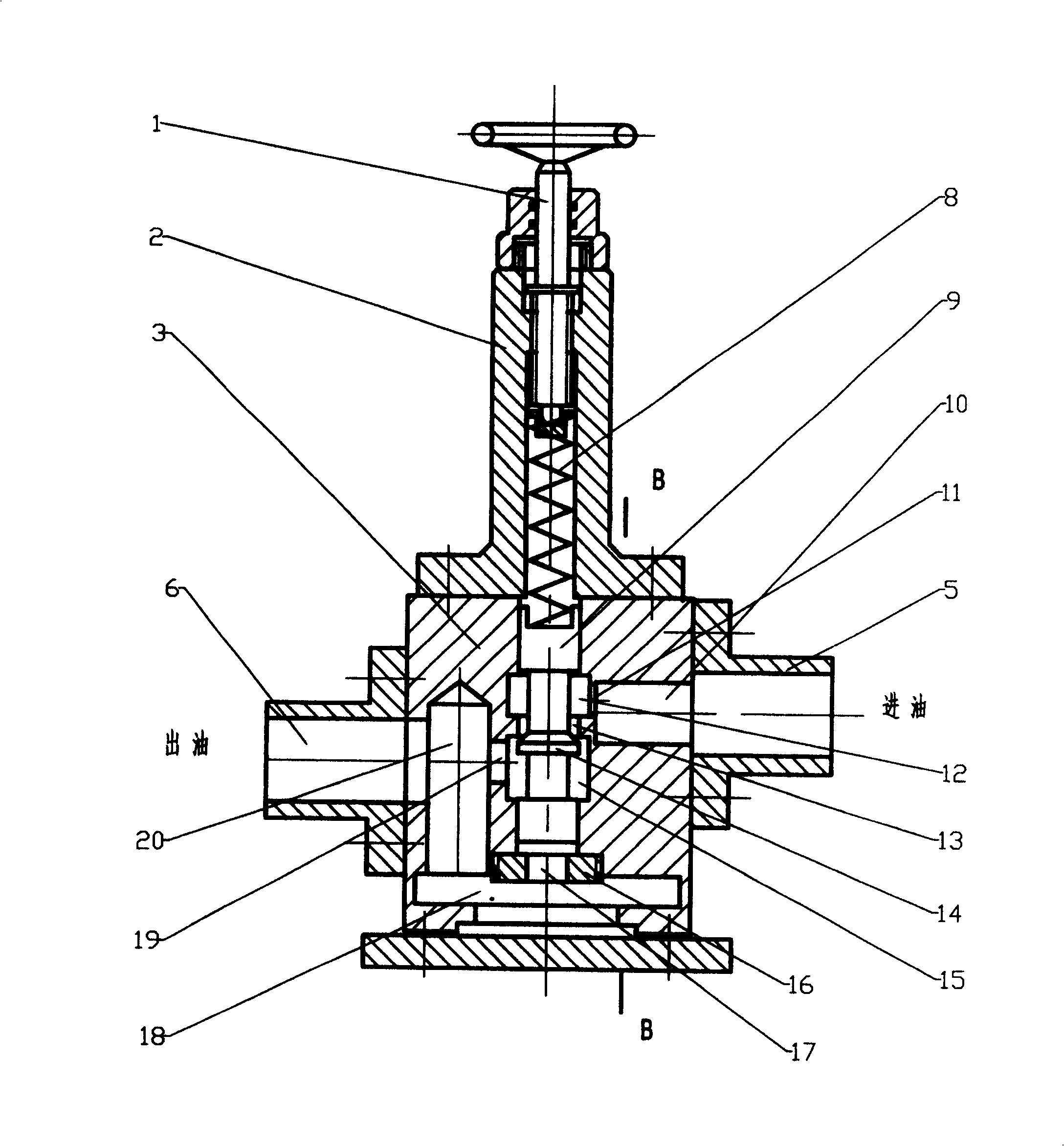
[0012] Such as Figure 1-4 The pressure-stabilizing pressure reducing valve shown is composed of automatic pressure-stabilizing adjusting rod 1, bonnet 2, valve body 3, manual regulating valve 4, spring 8, valve core 9 and other main components, among which the inner hole configuration of bonnet 2 is designed Spring 8 (as attached image 3 shown), and is adjusted by the automatic pressure-stabilizing adjustment lever 1, the spring is placed on the upper part of the valve core 9, and the conical boss on the valve core forms a cone door 14 to cooperate with the door seat hole 13 of the valve body, and the valve body A bottom plug 16 is arranged at the lower end, and a small hole 17 is arranged on the bottom plug 16 . The interaction between the pressure of the spring on the upper part of the spool and the oil pressure on the lower part of the spool controls the opening of the cone door 14 of the spool to automatically adjust the oil pressure. The valve body 3 is also provided w...


PUM


Abstract

A pressure-regulating pressure-reducing valve consists of a automatic pressure-regulating device and a hand control valve. The inlet end of the pressure-reducing valve is connected the main oil pump outlet of the generator to lead-in the high-pressure oil and the outlet end of the pressure-reducing valve is connected with the shaft seal oil-supply device of the generator. The output of the oil pressure is once completed controlled by the hand control valve. When the pressure lowers, the pressure-regulating device can be opened automatically to compensate pressure and make the pressure not change.

Description

Technical field [0001] The invention relates to a decompression device which decompresses the high-pressure oil output by the main oil pump of a generator set and uses it in a shaft seal oil supply system instead of an AC oil pump, in particular a dual-channel vibration-free pressure-stabilizing pressure-relief valve. Background technique [0002] At present, the structural form of the traditional pressure reducing valve is similar to the pressure stabilizing device of the present invention, and it is rarely used in the oil supply system of the generator shaft seal. The reason is that the system equipment is complicated and there are many pipelines. During use, it is easy to cause resonance with the system or jamming to cause oil cut-off, resulting in serious accidents of hydrogen run-off and hydrogen leakage. The generator is full of hydrogen, once it leaks, it will cause a fire or even an explosion. The function of the shaft seal oil supply system is to establish a sealing...

Claims


Application Information

Patent Timeline
Patent Type & Authority Patents(China)
IPC IPC(8): F16K17/168G05D16/00
Inventor 刘敬善
Owner 刘敬善
Learn More