Method for assigning antenna directional pattern utilized to cover wireless signal in room

An antenna pattern and indoor coverage technology, which is applied to antennas, radio relay systems, passive electrical relay systems, etc., can solve the problems of communication failure and complex structure, so as to reduce pressure, reduce transmission power, good handling effect

Inactive Publication Date: 2009-01-21
ZTE CORP
View PDF2 Cites 0 Cited by
  • Summary
  • Abstract
  • Description
  • Claims
  • Application Information

AI Technical Summary

Problems solved by technology

[0002] In the process of wireless communication, indoors are often blocked by buildings and walls, coupled with complex indoor structures, resulting in a large number of blind spots indoors, making normal communication impossible

Method used


Image

  • Method for assigning antenna directional pattern utilized to cover wireless signal in room
  • Method for assigning antenna directional pattern utilized to cover wireless signal in room
  • Method for assigning antenna directional pattern utilized to cover wireless signal in room

Examples


Embodiment Construction

[0017] The method of the present invention will be further described below in conjunction with the accompanying drawings.

[0018] The invention relates to a method for forming antenna pattern for indoor coverage of wireless signals. According to the path loss index and the height difference between the indoor antenna and the user antenna, the antenna pattern is shaped and adjusted to keep the signal in the coverage area constant.

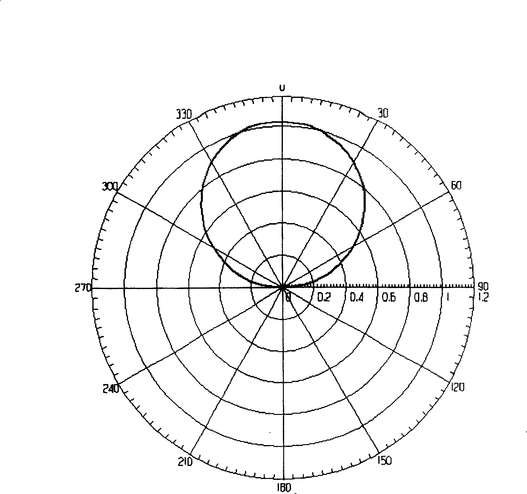
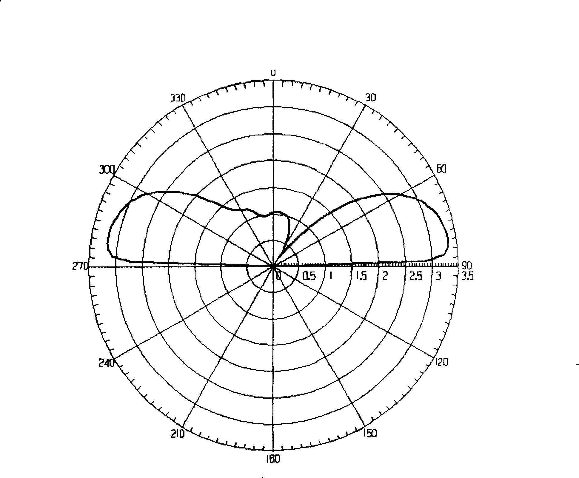
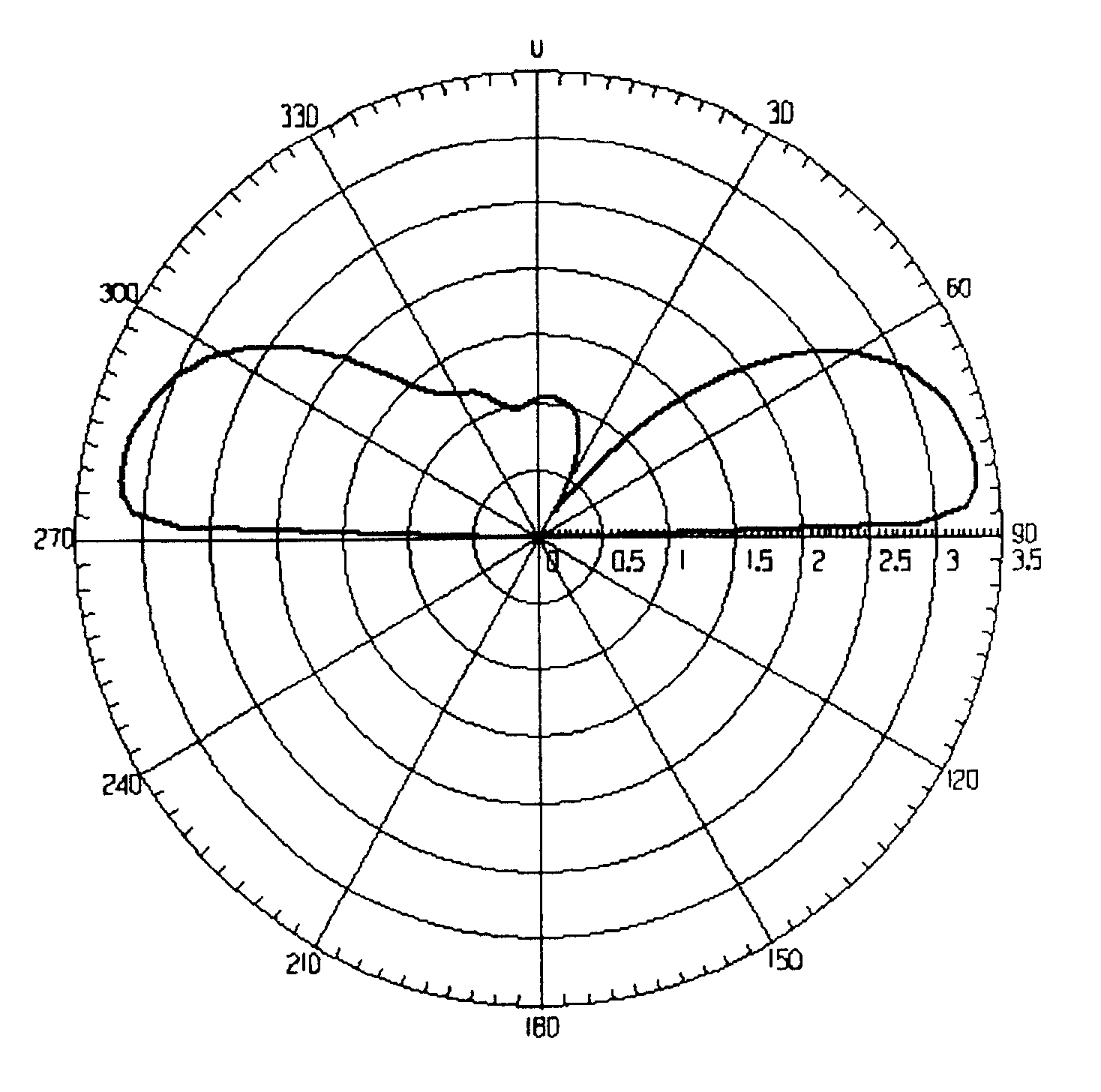
[0019] Specifically, in order to better illustrate the shape of the pattern of the indoor ceiling antenna, the characteristics of the pattern are described by the gain in each direction, and the gains are all gain values ​​in the same normalized state.

[0020] Define an angle θ. This angle is calculated in this way, taking the ceiling plane as a reference plane, taking the center point of the indoor antenna as a reference, and the angle between the line connecting the user and the center point and the ceiling plane. The direction of the maximum g...


PUM


Abstract

Based on index of path loss and height difference between indoor antenna and user antenna, adjusting assigned antenna pattern keeps constant signal in covered area. The assigning formula is: f (theta, phi) = CONST + 10nlg (h/sin theta), where theta and phi are relevant included angles, CONST is a constant. Indoor antenna is a transmitting antenna, and user antenna is an omnidirectional antenna installed on ceiling. The invention can reduce transmitting power in downward direction so as to reduce cost and power consumption as well as reduces interference on outdoor macro cellular system or other system, and reduces pressure of reverse chain amplifier. The invention makes possible to treat noise factor and linear relation.

Description

technical field [0001] The invention relates to a method for adjusting the indoor antenna radiation coverage of wireless signals, in particular to a method for shaping the indoor antenna pattern to achieve good indoor environment coverage during the wireless communication coverage process for the indoor environment. It belongs to the technical field of wireless communication. Background technique [0002] In the process of wireless communication, indoors are often blocked by buildings and walls, coupled with complex indoor structures, resulting in a large number of blind spots indoors, making normal communication impossible. The common method now is to introduce the forward signal into the indoor distribution system - set up antennas indoors, and then radiate out from the indoor antennas to maintain good indoor coverage; at the same time, the reverse signals are received by the indoor antennas and sent to the indoor distribution system to re-establish communication . [00...

Claims


Application Information

Patent Timeline
Patent Type & Authority Patents(China)
IPC IPC(8): H04B7/145H01Q3/00
CPCY02D30/70
Inventor 茹洪涛
Owner ZTE CORP
Why Eureka
Try Eureka