
Plate inserted coaxial micro-wave mode converter

A mode conversion and plug-in technology, applied in the direction of waveguide devices, electrical components, connecting devices, etc., can solve the problems of low power capacity, complex structure, difficult processing, etc., and achieve the effect of high power capacity, high power, and simple structure

Inactive Publication Date: 2009-02-04
SOUTHWEST JIAOTONG UNIV
View PDF3 Cites 0 Cited by
  • Summary
  • Abstract
  • Description
  • Claims
  • Application Information

AI Technical Summary

Problems solved by technology

Therefore, it has problems such as complex structure, difficult processing, local electric field concentration, and low power capacity.

Method used


Image

  • Plate inserted coaxial micro-wave mode converter
  • Plate inserted coaxial micro-wave mode converter
  • Plate inserted coaxial micro-wave mode converter

Examples


Embodiment 2

[0035] Figure 7 It is shown that the only difference between the structure of the mode converter in this example and the first embodiment is that the front end of the inner conductor 6 of the coaxial waveguide is tapered with a certain slope, and the rest of the structure is the same as that of the first embodiment. The structure is a circular waveguide TM 01 - Coaxial TEM transition section, so that the mode converter in this example can realize the circular waveguideTM 01 Mode-coaxial TEM mode transformation.

[0036] The specific design dimensions for the microwave mode conversion of 3.8 GHz in this embodiment are given below:

[0037] Circular waveguide TM with microwave source output frequency of 3.8GHz 01 mode, the waveguide radius is b=4.5cm. The front end of the inner conductor of the mode converter in embodiment 1 is designed as Figure 5 The shape of the cone shown, other parameters and dimensions are the same as the specific design in the first embodiment, and...


PUM


Abstract

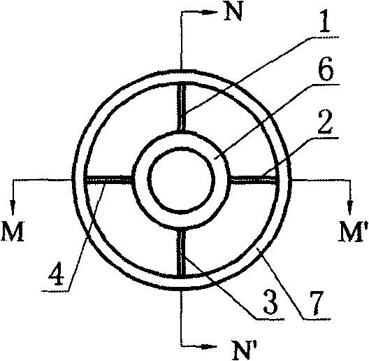
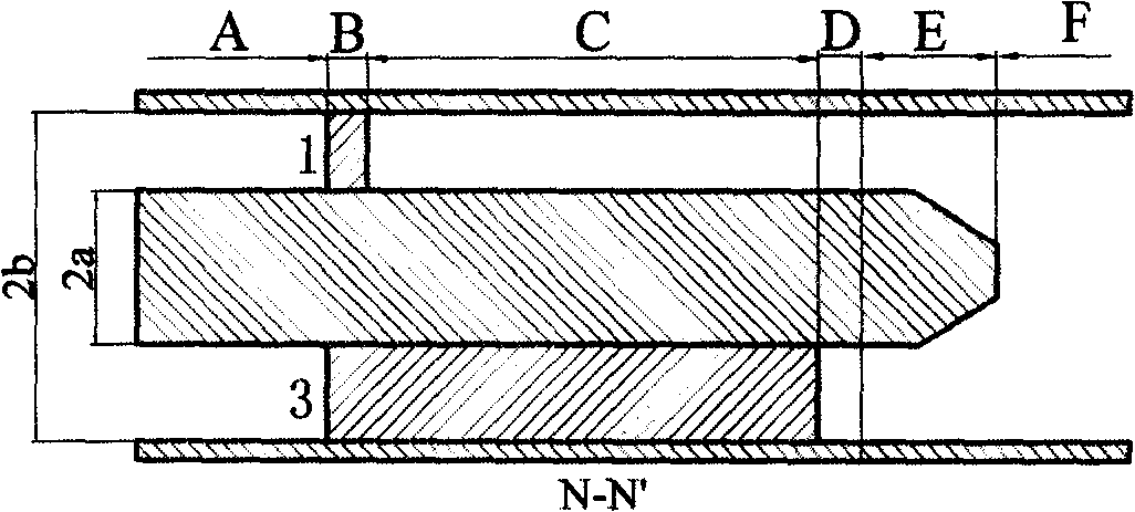
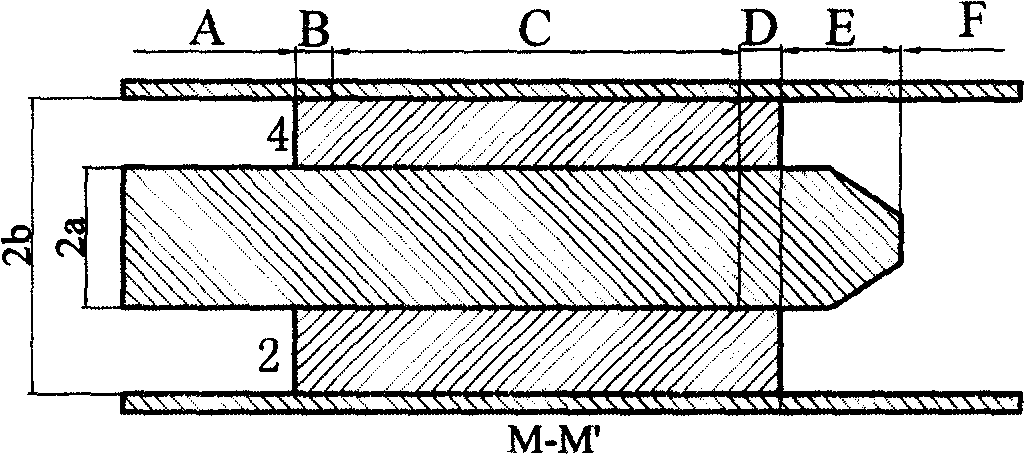
AT the place between inner and outer conductors of coaxial waveguide, along axial direction, the first, second, third and fourth metal plates are inserted. The angle between any neighboring plate is 90 degree. The first metal plate is shortest. The second and fourth metal plates are longest and have same length. The difference of metal plate length between third metal plate and first metal plate must meet following condition: the microwave electric field mode, in 180 degree scallop section waveguide composed of second and fourth metal plate, has a 180 degree phase difference with the microwave electric field mode, in 90 degree scallop section waveguide composed of second and third metal plate or third and fourth metal plate.

Description

technical field [0001] The invention relates to a high-power microwave mode converter, in particular to a TEM mode of a coaxial waveguide to a TE of a circular waveguide 11 mode converter. Background technique [0002] Most high-power microwave sources have rotationally symmetric structures, and the modes they generate are mostly rotationally axisymmetric modes. Devices such as transition tubes, magnetic insulated wire oscillators, and relativistic klystrons that use coaxial structures to output microwaves output coaxial TEM modes, while axially extracted virtual cathode oscillators, relativistic return wave tubes, and tapered slow wave structures The generator produces a circular waveguideTM 01 mold. Whether it is a coaxial TEM mode or a circular waveguide TM 01 Due to the rotational symmetry of the aperture field distribution at the output port, it will result in a ring-shaped far-field pattern with zero axial direction, which is not conducive to the directional transm...

Claims


Application Information

Patent Timeline
Patent Type & Authority Patents(China)
IPC IPC(8): H01P5/00
Inventor 刘庆想
Owner SOUTHWEST JIAOTONG UNIV
Learn More