Connecting method for metal plate, liquid crystal display protective cover and producing method thereof

A liquid crystal display and bonding method technology, which is applied in the direction of instruments, identification devices, nonlinear optics, etc., can solve the problems of light leakage in mechanical bonding parts, and achieve the effects of reducing material costs, excellent electrical conductivity, and firm bonding

Inactive Publication Date: 2009-02-11
SHIN EI SANGYO
View PDF5 Cites 1 Cited by
  • Summary
  • Abstract
  • Description
  • Claims
  • Application Information

AI Technical Summary

Problems solved by technology

But over time, the mechanical joints have the potential to leak light and are sometimes blamed for some weakness in terms of strength

Method used


Image

  • Connecting method for metal plate, liquid crystal display protective cover and producing method thereof
  • Connecting method for metal plate, liquid crystal display protective cover and producing method thereof
  • Connecting method for metal plate, liquid crystal display protective cover and producing method thereof

Examples


Embodiment 1

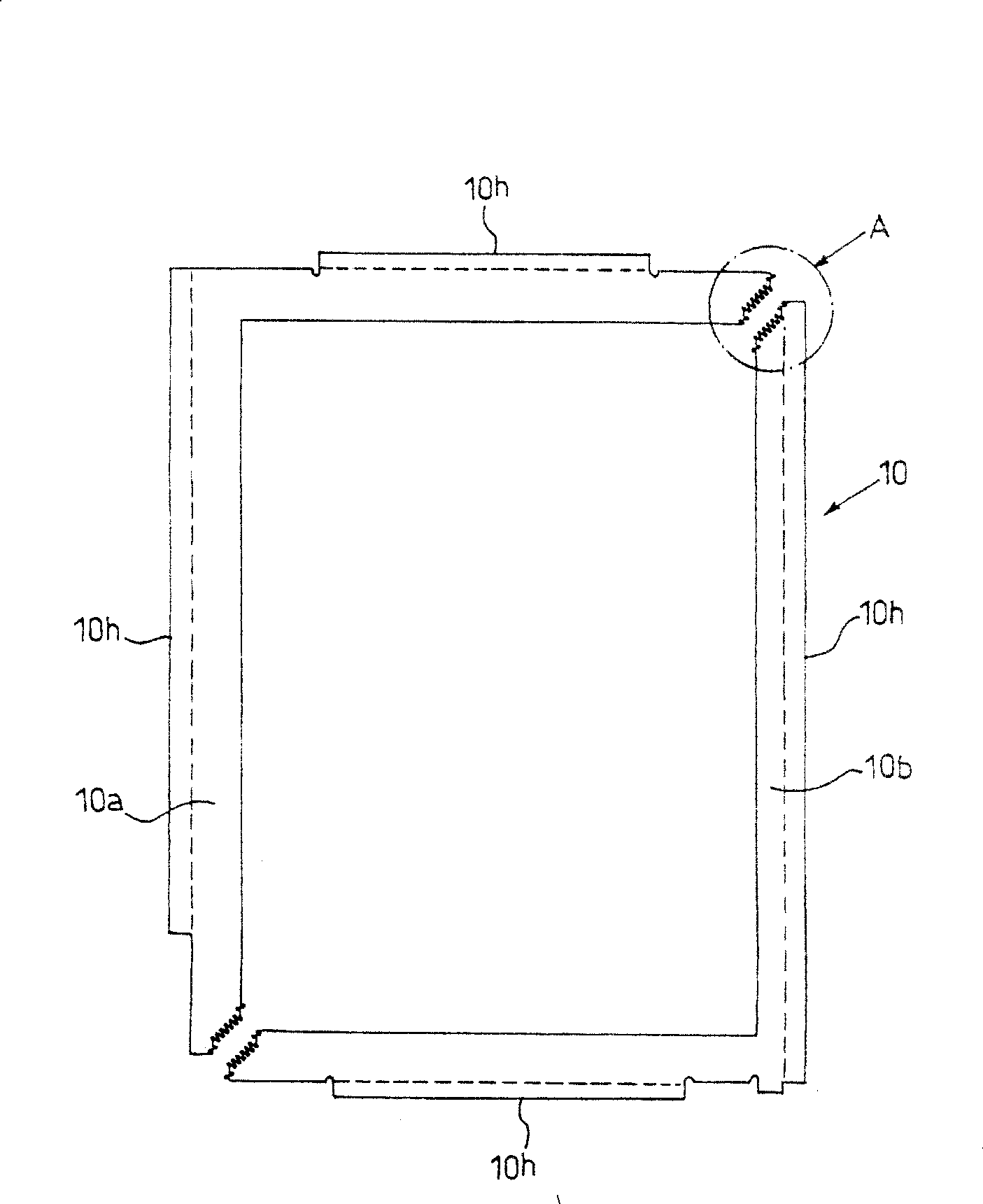
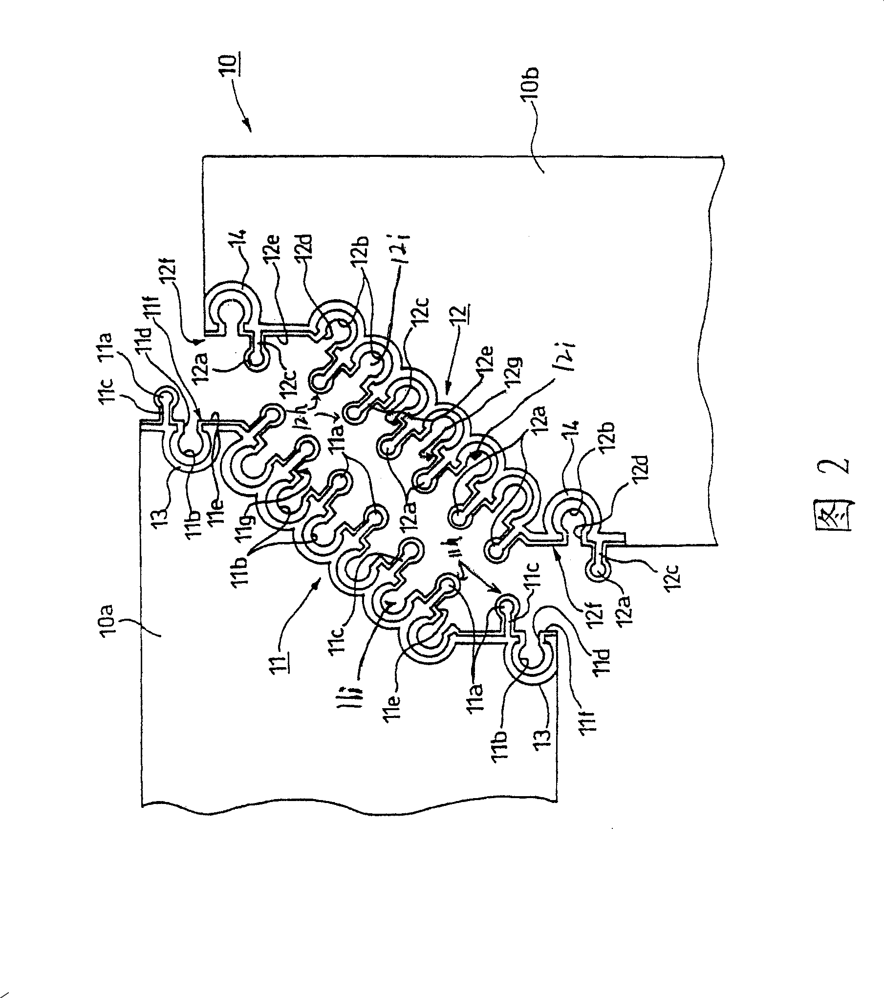
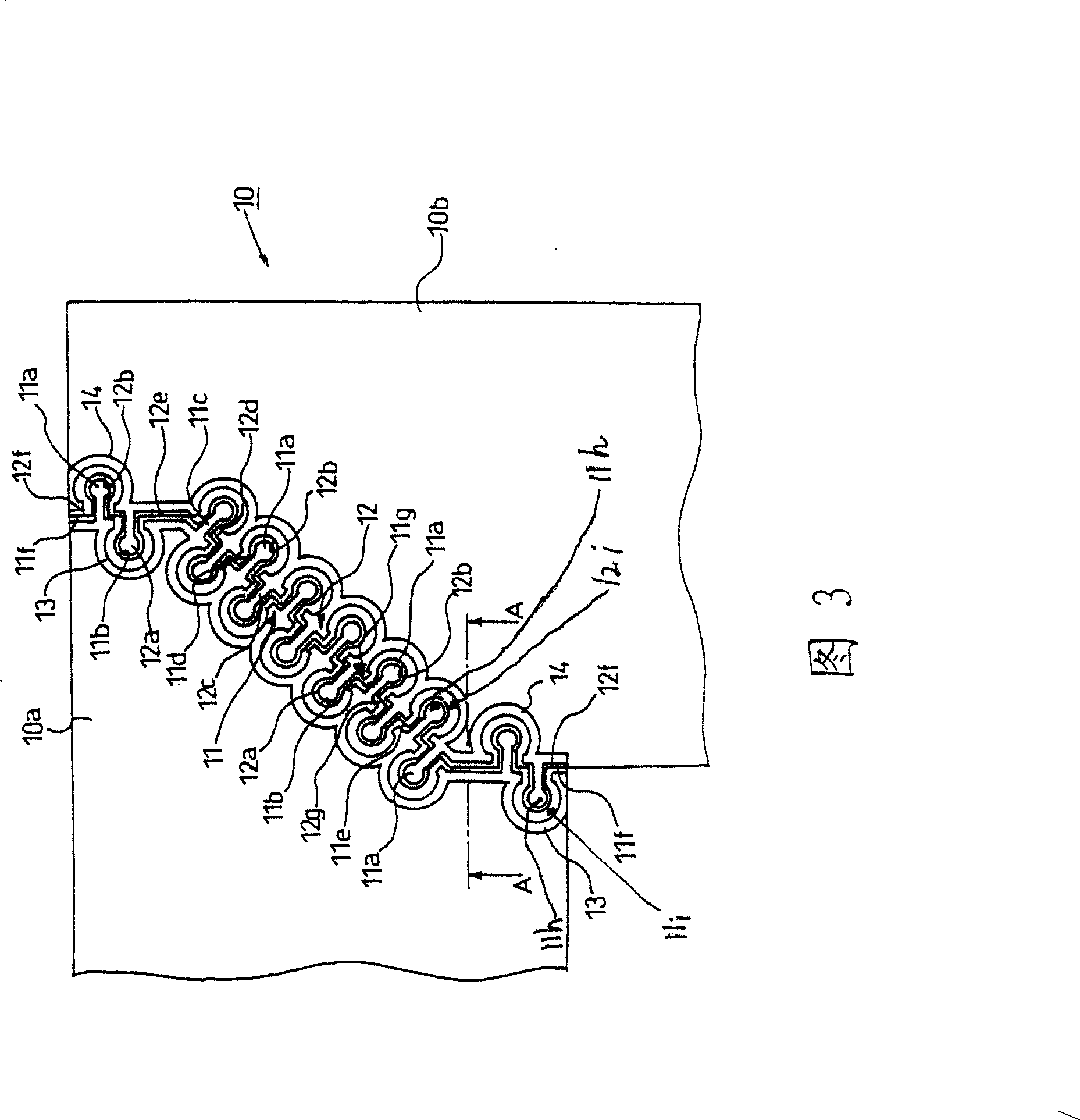
[0085] Figure 1 to Figure 7 An embodiment when the present invention is applied to an intermediate plate of a frame for a liquid crystal display cover is shown. It can be seen from the figure that in figure 1 When the structural members 10a, 10b constituting the following rectangular frame-shaped intermediate plate 10 are combined to form a frame, they are divided into two parts that are approximately L-shaped at the diagonal positions forming the corners. Each end portion of each end, especially as shown in Fig. 2 to Fig. 3, is provided with the fitting locking part that is constituted by the protruding part 11a, 12a that is approximately stud-shaped in planar shape and the recessed part 11b, 12b that is approximately stud-shaped 11, 12. Additionally, especially if figure 1 As shown, the parts that protrude to the outside of each side or are divided by dotted lines are as follows Figure 6 to Figure 7 The shown bending portion 10h when the cross section is bent into an...

Embodiment 2

[0133] Figure 14 In other embodiments, when a part of the intermediate plate 25 is in contact with the storage battery not shown in the figure, only the part in contact with the storage battery is made of gold, copper or a gold-plated conductive connection material 26. The embodiment 2 indicates that the fitting and locking portions 27 and 28 are in the form of straight lines, but a structure other than the structure of the fitting and locking portions shown in Embodiment 1 may also be used. In addition, the mark 26a is a contact part which contacts the storage battery which is not shown in a figure.

[0134] In the above embodiments, the case of implementing on the middle board has been described, but it can also be directly applied to the front board. According to needs, the present invention may be applied only to the middle board, or may be applied to both the middle board and the front board. When it is applied to both places, when it is divided into two places, the fi...


PUM

PropertyMeasurementUnit
thicknessaaaaaaaaaa
thicknessaaaaaaaaaa

Abstract

The present invention relates to an engaging and locking means by which a manufacturing cost of a shielding frame can be reduced to provide a joining method of plate materials made of metal preventing that light is leaked and insufficient strength is generated as much as possible, and to provide the shielding frame of a liquid crystal display using the joining method and to provide a manufacturing method of the shielding frame. Engaging and locking parts each having a plurality of projecting parts and recessed parts having leader parts and constricted parts and alternately provided are provided at respective joining end parts of the plate material made of metal and the shielding frame of the liquid crystal display which are to be joined along respective contours while upheaval parts are continuously or discontinuously formed. The projecting parts and the recessed parts of these engaging and locking parts are engaged with and connected to each other from a vertical direction and then the upheaval parts are crashed by caulking the engaged and connected parts from the vertical direction to integrally join the engaged and connected parts.

Description

technical field [0001] The present invention relates to a method of joining metal plates, a frame for a cover of a liquid crystal display, and a method for manufacturing the frame for the cover. Background technique [0002] The periphery and rear of the liquid crystal display are covered with a frame by the shroud, such as Figure 15 As shown, the shield frame 1 generally has a three-layer structure, and is composed of a frame-shaped front panel 1a at the front, a frame-shaped intermediate panel 1b in the middle, and a rear panel 1c at the rear. Thus, a structure in which the middle plate 1b is embedded in the front plate 1a is formed. In addition, there are cases where the intermediate board is omitted for small liquid crystal displays. In addition, the part indicated by the mark 2 is a liquid crystal display. [0003] The cross-sections of each side of the frame-shaped front panel 1a and the middle panel 1b are bent into an L-shape. The manufacturing process is as follo...

Claims


Application Information

Patent Timeline
Patent Type & Authority Patents(China)
IPC IPC(8): G02F1/1333G09F9/00
Inventor 沼泽硕夫石岛武寿
Owner SHIN EI SANGYO
Why Eureka
Try Eureka