
Device for generating belt like luminous source and application thereof

A technology for generating devices and light sources, applied in the directions of light guides, optics, optical components, etc., can solve the problems of uneven light, increased manufacturing cost, light loss, etc., and achieve the effects of improving display quality, increasing efficiency, and high uniformity

Inactive Publication Date: 2009-02-11
秦硕
View PDF22 Cites 0 Cited by
  • Summary
  • Abstract
  • Description
  • Claims
  • Application Information

AI Technical Summary

Problems solved by technology

The more light-emitting diodes are used, although the uniformity of light output can be improved, the manufacturing cost will also increase, and the point light source will cause serious light loss through multiple couplings of light guide plates and multi-layer optical films, which will increase relatively. The power consumption of the backlight module, therefore, there are still many problems to be solved when applying light-emitting diodes to the backlight module
[0007] U.S. Patent No. 5969343 discloses a linear lighting device applied to image scanners. In order to solve the problem of uneven light caused by the traditional linear light source with multiple LED arrays, a cylindrical guide and A linear light source device composed of a light emitter, the cylindrical guide is made of light-transmitting material, and a light scattering part is provided on a part of the side of the cylindrical guide, and the light emitter is arranged on an end surface of the cylindrical guide , the light emitted by the light emitter enters the interior of the cylindrical guide through the end face, and the light travels inside the cylindrical guide and is continuously reflected by its side. When part of the light enters the light scattering part, part of the light is scattered. Scattered light with an incident angle smaller than the critical angle with respect to the side of the cylindrical guide will enter the air and become illuminating light
The light-scattering part of the cylindrical guide part of the linear lighting device disclosed in the 343 case scatters the total reflected light, scatters the light incident therein to the air, and obtains the radiated light in the main scanning direction, which is applied to a scanner , can improve the problems caused by the linear light source of the traditional scanner array, but the linear lighting device disclosed by it, the incident light is scattered in the air, so the emitted light has no directivity, and cannot be used as a backlight light source of the liquid crystal panel
The disclosed planar light source device uses a plurality of light guide rods and point light sources as the light source unit, and the light emitted by the light source unit is reflected to the light emitting surface of the frame through the reflection plate below. This patent can also provide relatively uniform light, but The design of its frame and reflector actually increases the volume of the backlight module; moreover, the light guide bar only means that the angle between the incident light and the exit surface is below the critical angle, and it will not be completely on the exit surface of the light guide bar. Reflection, and does not propose how to obtain uniform or directional light, therefore, it is still impossible to realize the backlight source of the liquid crystal panel

Method used


Image

  • Device for generating belt like luminous source and application thereof
  • Device for generating belt like luminous source and application thereof
  • Device for generating belt like luminous source and application thereof

Examples


Embodiment 1

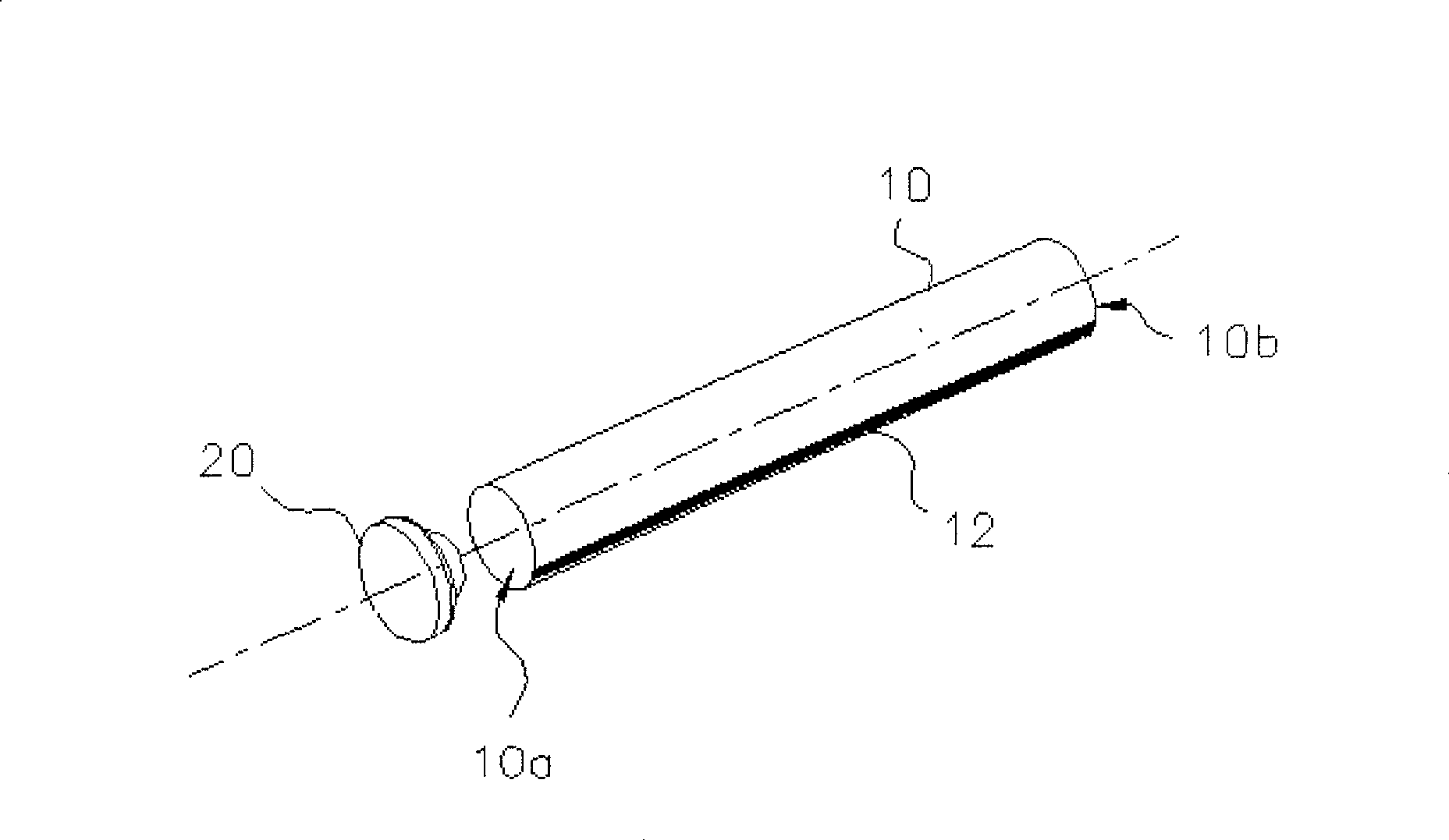
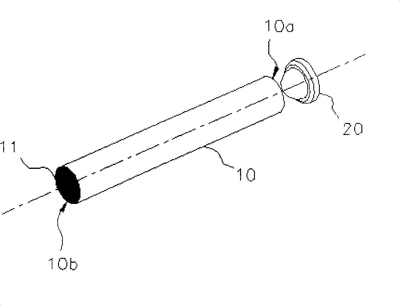
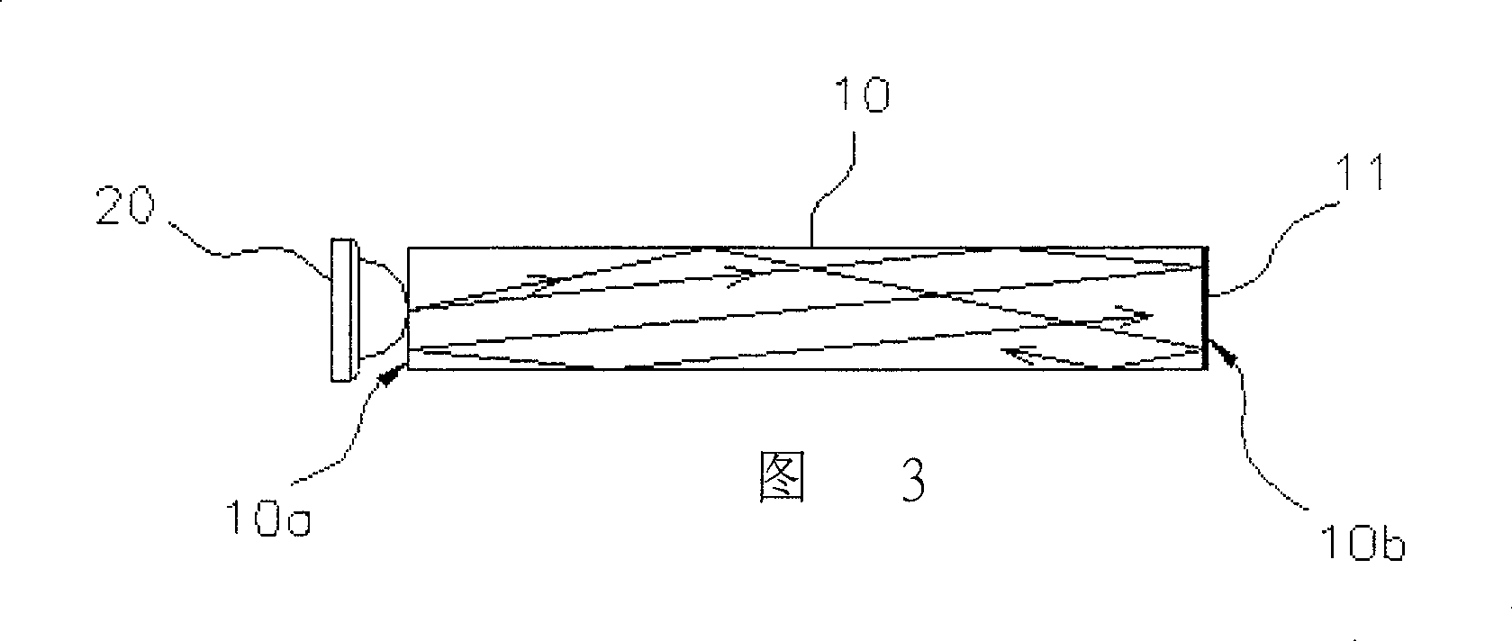
[0034] refer to figure 1 , 2 , the present embodiment consists of a light guide 10 and a light source 20; the light guide 10 is a cylinder made of transparent material, wherein the transparent material is optical acrylic (Polymethyl methacrylate, PMMA) or glass and other materials One end surface of the light guide 10 is defined as the incident surface 10a, and the opposite end surface is defined as the reflective surface 10b. The reflective surface 10b is covered with a reflective film 11. When light enters the light guide 10, the incident angle is greater than the critical angle. The light will be totally reflected with no luminous flux loss, and the light will also be incident on the reflective film 11 of the reflective surface 10b for specular reflection. Therefore, the light is continuously fully reflected in the light guide 10, and evenly fills the inside of the light guide 10 .

[0035] On the circumferential surface of the light guide body 10, a diffusion strip 12 is...

Embodiment 2

[0043] refer to Figure 9 In this embodiment, the reflective film 11 is not attached, but another light source 20 is arranged on the reflective surface 10b to increase the brightness of the light.

Embodiment 3

[0045] Referring to Figures 10A and 10B, in this embodiment, the width or position of the diffusion strip 12 can be changed according to different optical requirements, so as to change the range and directivity of the light output, and multiple diffusion strips 12 can also be added according to the optical requirements. As shown in the figure, two diffusion strips 12 correspondingly deviated from the normal line are arranged on the light guide body 10, and the two diffusion strips 12 have the same angle with respect to the normal line, and the light totally reflected in the light guide body 10, Respectively irradiated to the two diffuser strips 12 to scatter, because of the relationship between the relative angles of the diffuser strips 12, the scattered light rays are interlaced with each other, and the scattered light rays are gathered together through the light-emitting surface 13 to interleave the light, and the interlaced light rays will converge with each other, so that T...


PUM


Abstract

The invention discloses a band light source generator and its applications, the band light source generator consists of one light guide and at least one light-emitting source, the light guide is a cylinder made of light transmission materials, the surface of light guide has at least one diffusion strip, the other side opposite to this diffusion strip is a circular arc light exit surface; one end surface of light guide covered with a refracting film is defined as the refracting surface, the other end opposite to it is the incident surface, the light-emitting source is arranged on the incident surface of light guide. A plurality of the mentioned strip light source in parallel may be integrated into a light source to provide the adequate and uniform directional light ray, thus the optical films such as diffusion film or prism pieces etc may be omitted, moreover, for its low optical loss, compared with the long light guide, it may provide a uniform light source, so the invention is more suitable for large-size liquid crystal panel.

Description

technical field [0001] The invention relates to a light source device and its application, in particular to a strip light source device for generating directional light and its application. Background technique [0002] Liquid crystal display (LCD) has the advantages of low power consumption, low radiation, thin thickness, light weight, etc., and has gradually replaced the traditional picture tube display, and has become a widely used flat-panel display. The liquid crystal display itself is a non-self-illuminating display device, and it must rely on an external light source to achieve the display effect. The current liquid crystal display system uses a backlight module (Backlight) as an external light source, and the performance of the backlight module light source will directly affect the liquid crystal display. The display quality of the monitor. [0003] The existing backlight module is composed of light source, light guide plate, diffuser, prism sheet, reflector and oth...

Claims


Application Information

Patent Timeline
Patent Type & Authority Patents(China)
IPC IPC(8): G02F1/13357G02B6/00G02B5/02G02F1/1335
Inventor 秦硕
Owner 秦硕
Learn More