Supercharge Your Innovation With Domain-Expert AI Agents!

Method and apparatus for printing with identifying code of laser beam

A technology of identification codes and laser beams, applied in the field of printing and installation of identification codes using laser beams, can solve problems such as expansion of installation locations, reduction in productivity, deviation of irradiation points, etc., and achieve the effect of eliminating deviation of irradiation time difference and uniform concentration

Inactive Publication Date: 2009-02-11
TORAY ENG CO LTD
View PDF6 Cites 0 Cited by
  • Summary
  • Abstract
  • Description
  • Claims
  • Application Information

AI Technical Summary

Problems solved by technology

[0011] However, in the conventional printing method, as described above, when one laser beam is branched into multiple beams and the multiple laser beams are selectively irradiated to a predetermined position on the glass substrate, the stage on which the glass substrate is placed is relatively moved. , while proceeding, so the irradiation points of the beams tend to deviate from each other, because the deviation tends to disperse in the beam shape and energy, and the identification code cannot be printed into a uniform density and shape
[0012] In addition, in the existing printing method, the exposure unit with the laser beam irradiation mechanism and the platform carrying the substrate are relatively moved, and the irradiation identification code is scanned column by column to print, so when the liquid crystal panel is miniaturized, each substrate must When the number of panels arranged on the top increases, the number of scanning irradiations will inevitably increase, so there is a problem of lower productivity.
As a measure to prevent the decrease in productivity, it is conceivable to increase the number of exposure units installed for each printing device, but if only the number of installations is increased, the installation site needs to be enlarged and the device becomes bulky.

Method used


Image

  • Method and apparatus for printing with identifying code of laser beam
  • Method and apparatus for printing with identifying code of laser beam
  • Method and apparatus for printing with identifying code of laser beam

Examples


Embodiment 1

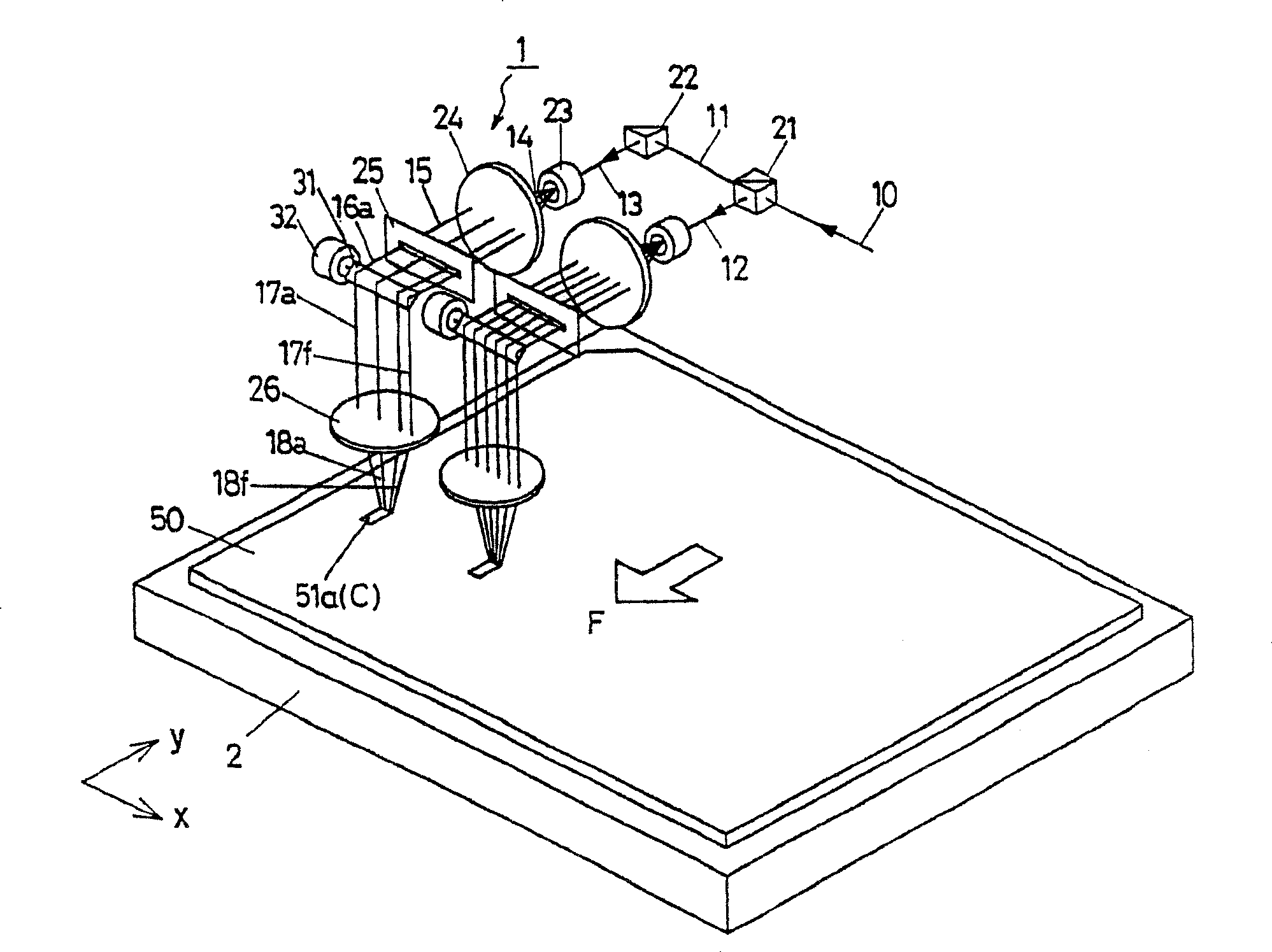
[0104] Using figure 1 When the identification code printing device of the company prints the identification code on the substrate coated with photoresist, as the laser beam, the laser beam near the wavelength λ=335nm of the third harmonic wave of the YAG laser is used as the laser beam coated on the substrate. A photoresist is chosen that is sensitive to that wavelength.

[0105] The pulse frequency f of the laser beam is set as f=60kHz, the width of the working surface of the laser beam when it is set to focus on the substrate is W=0.050mm, and the interval between adjacent beams is p=0.050mm. The speed v=500 mm / sec for moving the table in the thickness direction.

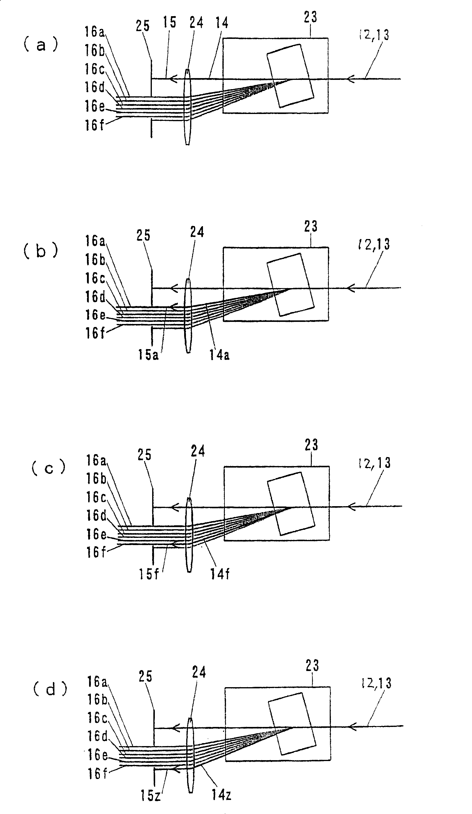
[0106] In addition, the laser beam is deflected 7 stages by the beam deflection mechanism, and the beams in 6 directions are irradiated on the substrate through the transmission filter 25, and the beams in 6 directions are selectively irradiated at 10 kHz.

[0107] According to the above setting, the distance D...

Embodiment 2

[0122] Using Figure 17 When printing the identification code on the substrate, the printing device uses a laser beam with a wavelength λ=355nm of the third harmonic of the YAG laser as the laser beam, and selects this wavelength as the photoresist coated on the substrate. Photosensitive resin.


PUM


Abstract

A method and device for marking an identification code on an article to be marked on a stage by means of a laser beam. The laser beam outputted from an exposure unit is so scanned as to deflect in time series in order in a direction perpendicular to the relative movement direction with respect to the stage. The irradiation is shifted synchronously in the relative movement direction. The irradiated points on the article are arranged like orthogonal coordinates. Another method and device is for marking arrays of identification codes while one exposure unit is moving by one pitch in the relative movement direction.

Description

[0001] This application is a divisional application of: [0002] Title of invention: Method and device for printing identification codes using laser beams [0003] Application date: October 24, 2002 [0004] Application number: 02821192.8 technical field [0005] The present invention relates to a printing method and device for printing an identification code on a marked article with a laser beam, and more specifically, to printing a photoresist-coated substrate with a laser beam for use in a liquid crystal panel manufacturing process or the like. A method and device for printing identification codes for history management, quality control, etc. Background technique [0006] Generally speaking, in the liquid crystal panel manufacturing process, for the glass substrate coated with photoresist (ie, photosensitive resin), in addition to exposing the circuit pattern with the pattern exposure device, the identification code exposure device is used to identify the substrate. co...

Claims


Application Information

Patent Timeline
Patent Type & Authority Patents(China)
IPC IPC(8): G03F7/20G02B26/10
Inventor 佐藤谦二森诚树植原幸大
Owner TORAY ENG CO LTD
Features
  • R&D
  • Intellectual Property
  • Life Sciences
  • Materials
  • Tech Scout
  • Unparalleled Data Quality
  • Higher Quality Content
  • 60% Fewer Hallucinations
Learn More