Multi-interface flow-balance controlling method

A technology of flow balance and control method, which is applied in the direction of digital transmission system, electrical components, transmission system, etc., and can solve the problems of unbalanced interface requirements and inability to make full use of system resources.

Active Publication Date: 2009-02-11
HUAWEI TECH CO LTD
View PDF4 Cites 0 Cited by
  • Summary
  • Abstract
  • Description
  • Claims
  • Application Information

AI Technical Summary

Problems solved by technology

[0012] The technical problem to be solved by the present invention is to provide a multi-interface flow balance control method to overcome the shortcomings of the existing flow control technology that cannot make full use of system resources and cannot balance the needs of each interface

Method used


Image

  • Multi-interface flow-balance controlling method
  • Multi-interface flow-balance controlling method
  • Multi-interface flow-balance controlling method

Examples


Embodiment Construction

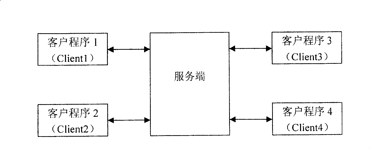
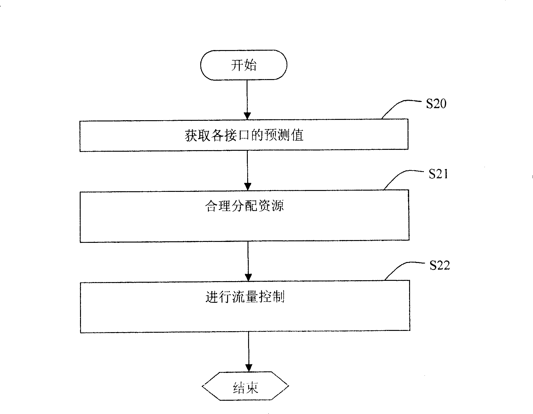
[0029] The present invention provides a multi-interface flow balance control method, such as figure 2 shown, is the main flow diagram of the present invention. The present invention firstly predicts the flow of each interface according to the current network condition, then allocates resources according to the predicted flow forecast value and the priority of each interface, and obtains a flow control threshold for each interface, and after allocating resources The flow of each interface is controlled by the flow control threshold of each interface.

[0030] First, in step S20, the traffic prediction value of each interface is obtained. Obtaining the traffic forecast value of each interface in the next period is a prerequisite for performing traffic control on each interface. For the convenience of description, one second is taken as one cycle for description below, but the present invention is not limited to this, and an integer number of seconds can be taken as one cycle....


PUM


Abstract

The method includes steps: (1) based on value of actual flow at previous cycle at each interface in server end to obtain predicted value of flow at next cycle; (2) at least based on predicted value of flow at each interface, assigning system resources for each interface, and determining threshold of flow control at each interface; (3) determining whether flow of data packet received in next cycle at each interface exceed threshold of flow control; if yes, starting to discard received data packet till to next cycle. The invention makes system resources possible to distribute to each interface smoothly so as to take full advantage of system resources. Predicting flow at each interface simplifies process for each data packet so as to reduce occupancy rate of CPU.

Description

technical field [0001] The present invention relates to a method for controlling network traffic, in particular, to a multi-interface traffic balance control method. Background technique [0002] The application program (Service) running on the server side generally connects with multiple client programs (Client) at the same time, such as figure 1 Shown is a schematic diagram of a typical server-side and client-side architecture. As the network traffic of the client continues to increase, the load of the client continues to increase, which will occupy more system resources (such as CPU occupancy rate), which will affect the server itself and all other applications running on the server. The efficiency can even lead to server downtime in severe cases. In order to avoid this situation, the application itself needs to adopt a certain flow control strategy to control its utilization of system resources. In addition, how to utilize limited resources reasonably and effectively ...

Claims


Application Information

Patent Timeline
Patent Type & Authority Patents(China)
IPC IPC(8): H04L12/56H04L12/801
Inventor 王华聂保华武敏
Owner HUAWEI TECH CO LTD
Why Eureka
Try Eureka