Construction method for pulling-resistant and pressure-resistant slip casting pipe pile

A construction method and grouting pipe technology, which are applied in sheet pile walls, infrastructure engineering, construction, etc., can solve the problems of insufficient anti-buoyancy and water seepage of the bottom plate and insufficient pull-out resistance of uplift piles.

Inactive Publication Date: 2009-02-18
何新东
View PDF4 Cites 0 Cited by
  • Summary
  • Abstract
  • Description
  • Claims
  • Application Information

AI Technical Summary

Problems solved by technology

[0003] The purpose of the present invention is to solve the problems of buildings built in strata with complex geological conditions or high groundwater levels, when the floor of the building has insufficient buoyancy resistance to water seepage of the floor, the design eccentricity of the building is too large to cause inclination, and when a new building is designed for anti-floating Insufficient pullout strength of pullout piles, providing a construction method for pullout and compression grouting pipe piles

Method used


Image

  • Construction method for pulling-resistant and pressure-resistant slip casting pipe pile
  • Construction method for pulling-resistant and pressure-resistant slip casting pipe pile
  • Construction method for pulling-resistant and pressure-resistant slip casting pipe pile

Examples


specific Embodiment approach 1

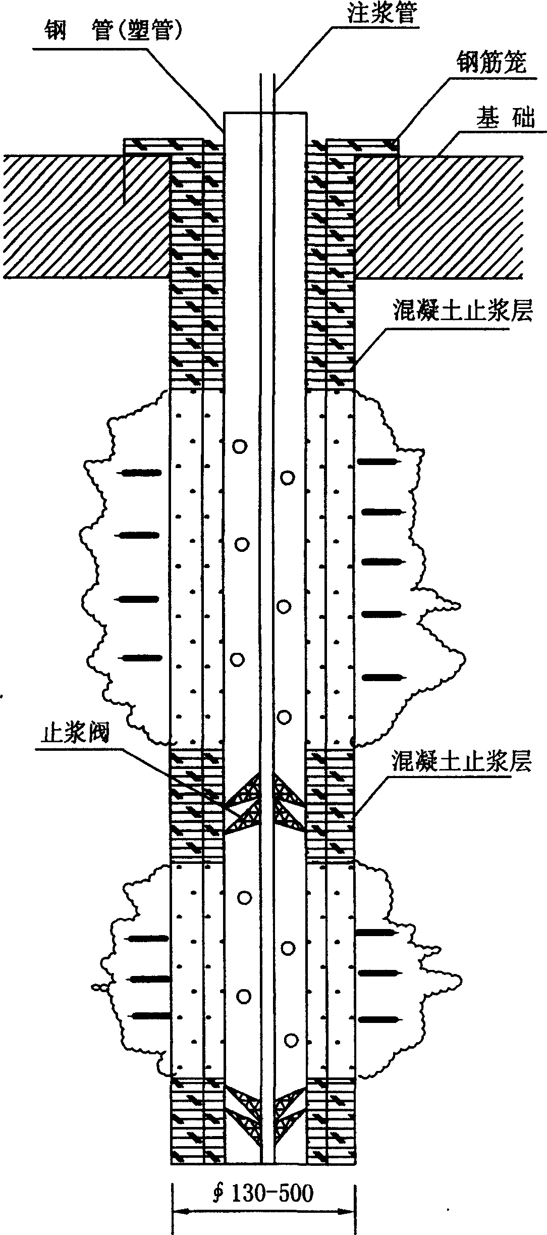
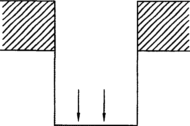
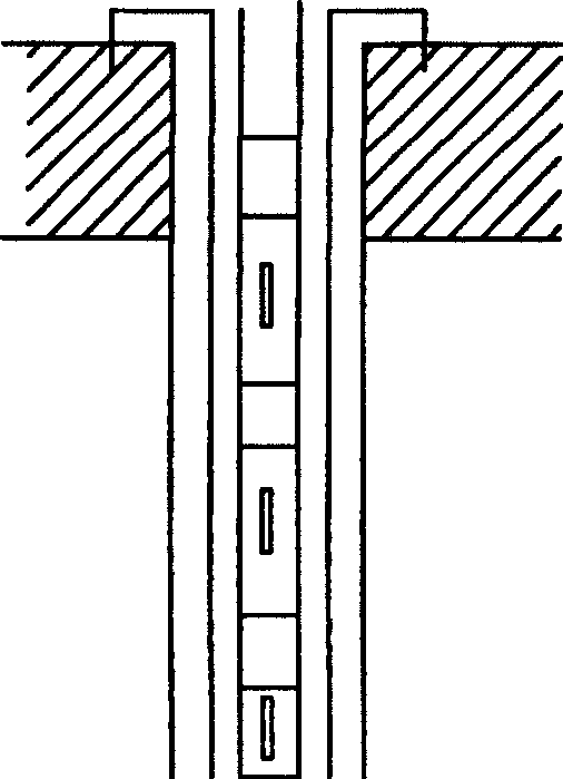
[0005] Specific implementation mode one: (see Figure 1 to Figure 6 ) The method of the present embodiment is realized through the following steps: one, according to the design elevation and aperture of pile, drill down on the foundation layer of building; Two, enter the steel pipe with grouting hole in the hole after forming or plastic pipe, the position of the steel pipe or plastic pipe is centered in the hole; 3. Insert steel bars or reinforcement cages into the hole outside the steel pipe or plastic pipe; 4. In the space between the outer wall of the steel pipe or plastic pipe and the wall of the hole Put sand or gravel into it; 5. Put a grouting pipe with a grout stop valve in the steel pipe or plastic pipe; 6. Start the grouting pump and start grouting into the pile hole; The effective (welding) connection between the steel bar or steel cage and the foundation layer of the building is carried out and the pile is sealed and waterproofed.

specific Embodiment approach 2

[0006] Embodiment 2: In this embodiment, the diameter Φ of the steel pipe or plastic pipe is 50-150 mm. Others are the same as in the first embodiment.

specific Embodiment approach 3

[0007] Embodiment 3: In this embodiment, hoops are fixed on the outer wall of the steel pipe or plastic pipe, and the distance between the hoops is 50 cm. A hoop is fixed on the outer wall of the steel pipe or the plastic pipe to improve the frictional force with the concrete of the pile body. Others are the same as in the first embodiment.


PUM


Abstract

A construction method of casting pipe pile plucking with resistance to plucking and pressing, The invention relates to a construction method of pipe pile. The purpose of the invention is: solving the insufficient problems of resistance to plucking and pressing happened in the buildings which are built under complex geological conditions or under higher groundwater level geological strata and the problems are generated by bottom board percolating water due to buildings bottom board plucking resistance is insufficient, declination due to excessive eccentricity when design buildings and when design the resistance to plucking of new buildings. The invention drills hole downward on the buildings basic layer according the design height mark and bore diameter of pipe pile, lifts downward steel pipes or plastic pipes with slip casting hole after the drilled hole is completed, lifts downward reinforcement bar or reinforcement cage in the hole out the steel pipes or plastic pipes, lifts downward sands and broken stone between the outer wall of the steel pipes or plastic pipes and the hole wall. The invention has extremely distinctive action in buildings plucking-resistance and reinforcement, buildings declination correction and the foundation reinforcement project of house floors addition and reconstruction. The pile type in the invention is suitable for various geological strata, it can be used for the plucking-resistance, reinforcement and foundation reinforcement of prior buildings and the resistance-plucking pile construction of new buildings.

Description

technical field [0001] The invention relates to a construction method of pipe piles. Background technique [0002] Buildings built on strata with complex geological conditions or high groundwater levels often have the following problems: first, the anti-floating design of the building floor is insufficient, causing cracks and water seepage in the floor; second, the design of the entire building is too eccentric to cause inclination The third is that the uplift resistance of the uplift piles is insufficient when the new buildings are designed for anti-floating. None of the current prevention or treatment methods can completely solve the above problems. Contents of the invention [0003] The purpose of the present invention is to solve the problems of buildings built in strata with complex geological conditions or high groundwater levels, when the floor of the building has insufficient buoyancy resistance to water seepage of the floor, the design eccentricity of the buildin...

Claims


Application Information

Patent Timeline
Patent Type & Authority Patents(China)
IPC IPC(8): E02D5/34E02D5/62
Inventor 何新东
Owner 何新东
Why Eureka
Try Eureka