
Chip packaging structure and manufacturing method therefor

A technology of chip packaging and manufacturing method, which is applied in semiconductor/solid-state device manufacturing, electrical components, electrical solid-state devices, etc., can solve the problems of contaminating the first surface of circuit substrates, overflowing glue, and increasing the cost of molds, so as to improve the phenomenon of glue overflowing. , the effect of reducing manufacturing costs

Inactive Publication Date: 2009-02-18
CHIPMOS TECH INC
View PDF3 Cites 0 Cited by
  • Summary
  • Abstract
  • Description
  • Claims
  • Application Information

AI Technical Summary

Problems solved by technology

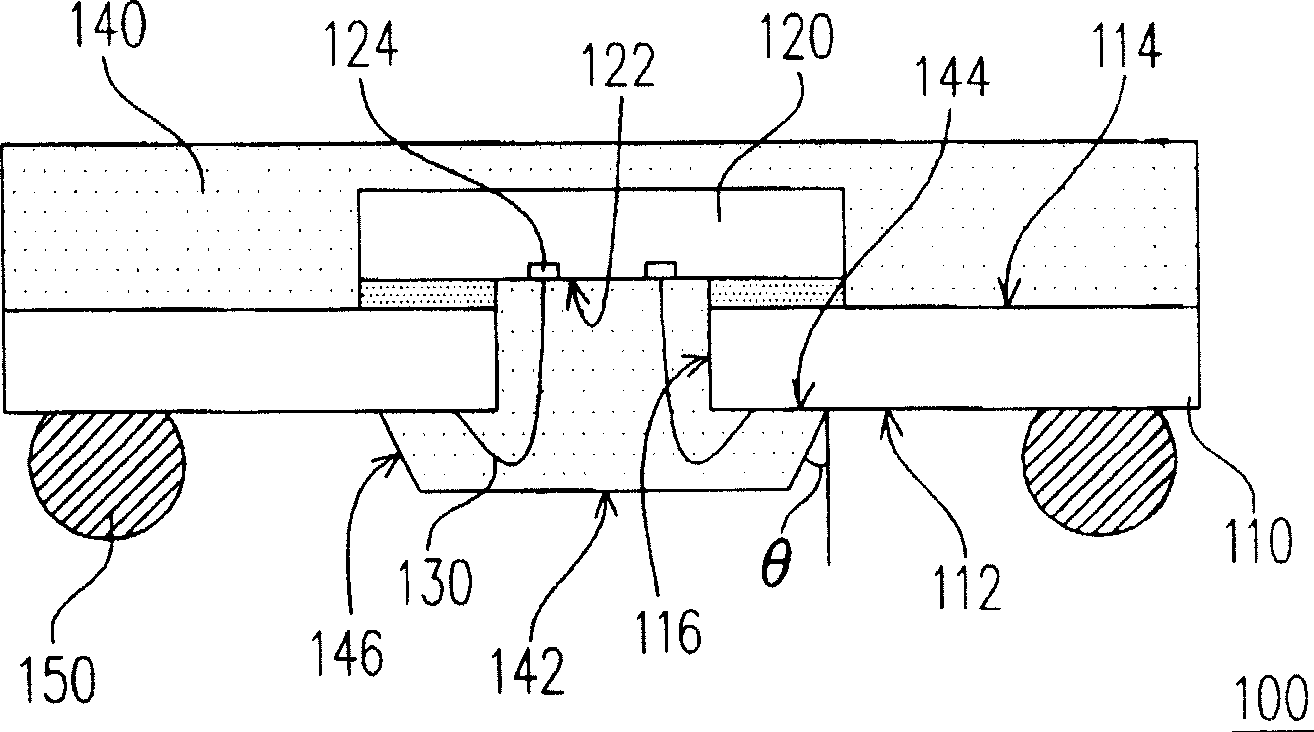
Therefore, when performing the sealing process, the upper and lower parts of the molds used for the chip packaging structure 100 of different sizes have inconsistent shapes, which will increase the cost of mold making.
In addition, during the encapsulation process, sometimes glue overflow (flash) phenomenon occurs to contaminate the first surface 112 of the circuit substrate 110

Method used


Image

  • Chip packaging structure and manufacturing method therefor
  • Chip packaging structure and manufacturing method therefor
  • Chip packaging structure and manufacturing method therefor

Examples


Embodiment Construction

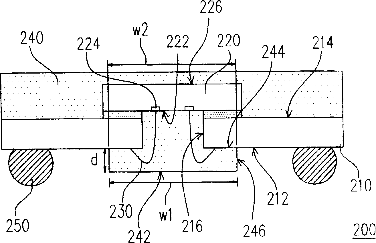
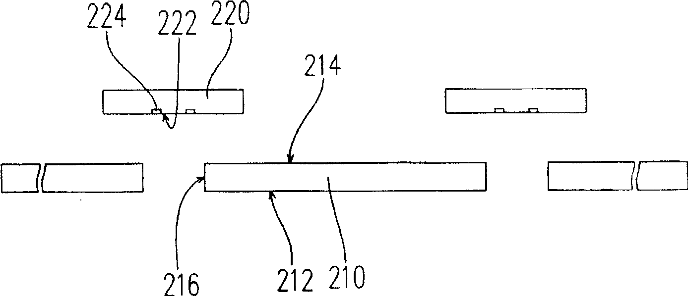
[0034] See figure 2 As shown, it is a schematic cross-sectional view of a chip package structure according to an embodiment of the present invention. The chip package structure 200 of this embodiment includes a circuit substrate 210, a chip 220, a plurality of bonding wires 230, and a glue 240. The circuit substrate 210 has a first surface 212, a second surface 214 and a through hole 216, wherein the through hole 216 connects the first surface 212 and the second surface 214. The chip 220 is disposed on the circuit substrate 210, and the chip 220 has an active surface 222 and a plurality of bonding pads 224, wherein the bonding pads 224 are disposed on the active surface 222, and the second surface 214 of the circuit substrate 210 and the active surface of the chip 220 The surfaces 222 are opposite to each other, and the through holes 216 expose the solder pads 224.

[0035] The bonding wires 230 respectively connect the bonding pads 224 and the first surface 212 of the circuit su...


PUM


Abstract

The present invention relates to a manufacturing method for the wafer encapsulation structure, and includes the following steps: firstly, a circuitry substrate with a first surface, a second surface and a through-hole connected with the two surfaces are provided. Secondly, a wafer with an active surface and a plurality of welding washers arranged on the active surface are provided. Thirdly, the wafer is fixed on the circuitry substrate, the second surface is face to face with the active surface, and the through-hole exposes the welding washers. Fourthly, a plurality of welding lines passed the through-hole and connected electrically with the welding washers and the first surface are formed. Fifthly, a film layer with one opening hole is formed on the first surface. The opening hole exposes the welding lines, the welding washers and the through-hole and a part of the first surface. Sixthly, a colloid is formed inside the opening hole and the through-hole to pack a part of the active surface, the welding lines and a part of the first surface. Lastly, the film layer is removed. Thereby the colloid overflow phenomenon can be mended, and the manufacturing cost can be reduced.

Description

Technical field [0001] The invention relates to a semiconductor element and a manufacturing method thereof, in particular to a chip packaging structure and a manufacturing method thereof. Background technique [0002] In the semiconductor industry, the production of integrated circuits (IC) can be divided into three stages: IC design, IC process, and IC package. [0003] In the production of integrated circuits, a chip is completed through the steps of wafer production, integrated circuit formation, and wafer sawing. The wafer has an active surface, which generally refers to the surface of the wafer with active components. After the integrated circuit inside the wafer is completed, the active surface of the wafer is further equipped with a plurality of bonding pads, so that the final chip formed by wafer dicing can be electrically connected to an external through these bonding pads. Carrier (carrier). The carrier is, for example, a lead frame or a package substrate. The chip can ...

Claims


Application Information

Patent Timeline
Patent Type & Authority Patents(China)
IPC IPC(8): H01L21/60H01L21/56H01L23/498H01L23/31
CPCH01L2924/15311H01L2224/4824H01L2224/73215H01L2224/32225H01L2924/00012H01L2924/00
Inventor 林俊宏周世文潘玉堂
Owner CHIPMOS TECH INC
Learn More