
Magnetic core structure capable of reducing insertion loss

A technology of insertion loss and magnetic core, applied in the direction of transformer/inductor magnetic core, etc., can solve the problems of large signal insertion loss and circuit interference, etc.

Pending Publication Date: 2018-07-10
TAI TECH ADVANCED ELECTRONICS SI HONG
View PDF1 Cites 0 Cited by
  • Summary
  • Abstract
  • Description
  • Claims
  • Application Information

AI Technical Summary

Problems solved by technology

This capacitance is easy to cause circuit interference, and the insertion loss of the signal is large.

Method used


Image

  • Magnetic core structure capable of reducing insertion loss
  • Magnetic core structure capable of reducing insertion loss
  • Magnetic core structure capable of reducing insertion loss

Examples


Embodiment Construction

[0017] The present invention will be described in detail below in conjunction with the accompanying drawings and specific embodiments, wherein the schematic embodiments and descriptions are only used to explain the present invention, but are not intended to limit the present invention.

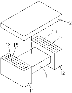
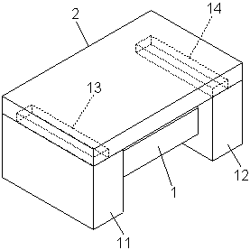
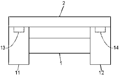
[0018] Such as Figure 1 to Figure 3 As shown, a magnetic core structure capable of reducing insertion loss includes: a magnetic core body 1 and a magnetic core cover 2 .

[0019] The two sides of the magnetic core body 1 are respectively extended with a first flange 11 and a second flange 12 , and the first flange 11 and the second flange 12 can be three-dimensional rectangles. The first flange 11 is provided with a first groove 13, and the second flange 12 is provided with a second groove 14, and the first groove 13 and the second groove 14 are respectively arranged on the first flange. Flange 11 and the same side 15, 16 direction of the second flange 12. The magnetic core cover 2 is adjac...


PUM


Abstract

The invention relates to a magnetic core structure capable of reducing the insertion loss. The magnetic core structure comprises a magnetic core body and a magnetic core cover body, wherein two sidesof the magnetic core body are respectively provided with a first flange and a second flange in an extending manner, the first flange is provided with a first groove, the second flange is provided witha second groove, and the first groove and the second groove are respectively arranged on the same side surface of the first flange and the second flange; and the magnetic core cover body is adjacentto the first groove and the second groove, and the magnetic core cover body is combined onto the same side of the first flange and the second flange. The magnetic core structure is simple in structureand reasonable in design; and by adopting the magnetic core structure, the overflow rubber can be improved, the parasitic capacitance generated by a coil winding can be reduced, the insertion loss ofa signal can be reduced, the electric (magnetic) characteristics are good, the stability of the product yield can be maintained, and an efficacy can be achieved.

Description

【Technical field】 [0001] The invention relates to a magnetic core structure, in particular to a magnetic core structure capable of reducing insertion loss. 【Background technique】 [0002] Inductor, Common Mode Choke or Transformer are often used in electronic products. In the electronic circuit, it has the functions of resisting current changes, filtering current noise, stabilizing the current value in the circuit, reducing electromagnetic interference (EMI), and power conversion. [0003] In this regard, China Taiwan Patent No. M445243 discloses an "inductance element". The adhesive can be made of thermosetting adhesive, thermoplastic adhesive, silicone adhesive, etc., and an enameled wire is wound on the I-shaped iron core to form an inductance element. [0004] In this technical solution, when the adhesive is used for the bonding (contact surface) between the I-shaped iron core and the cover plate iron core, no matter how much the adhesive is applied, when the I-shaped ...

Claims


Application Information

Patent Timeline
IPC IPC(8): H01F27/24
CPCH01F27/24
Inventor 谢明谚杨祥忠林锦政罗宜春
Owner TAI TECH ADVANCED ELECTRONICS SI HONG
Learn More