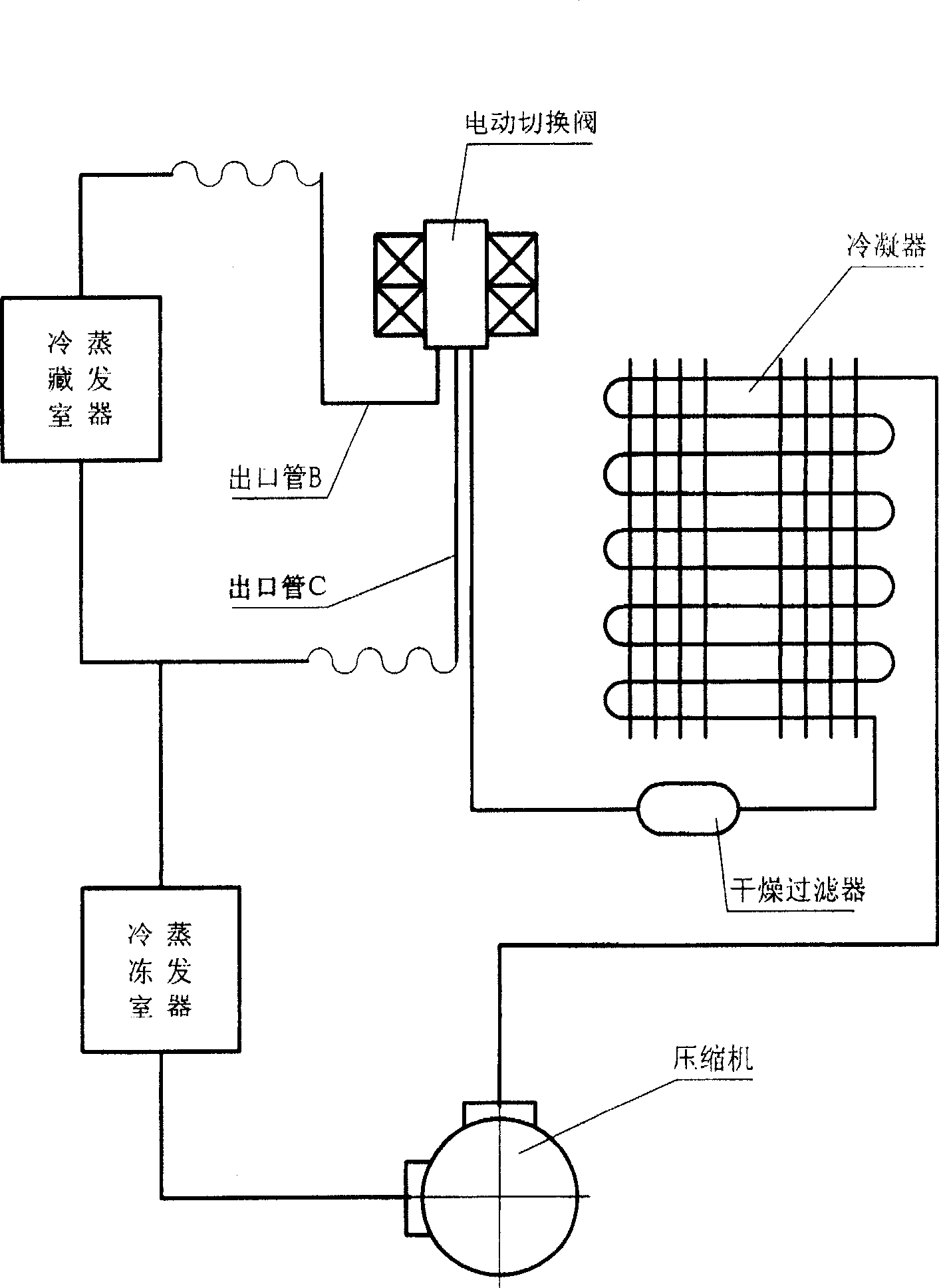
Electric change-over valve
An electric switching, valve cavity technology, applied in valve details, multi-port valves, valve devices, etc., can solve problems such as difficult processing and complex structure, reduce contact area, reduce product volume, and reduce driving force. Effect
- Summary
- Abstract
- Description
- Claims
- Application Information
AI Technical Summary
Problems solved by technology
Method used
Image

Examples
Embodiment 1
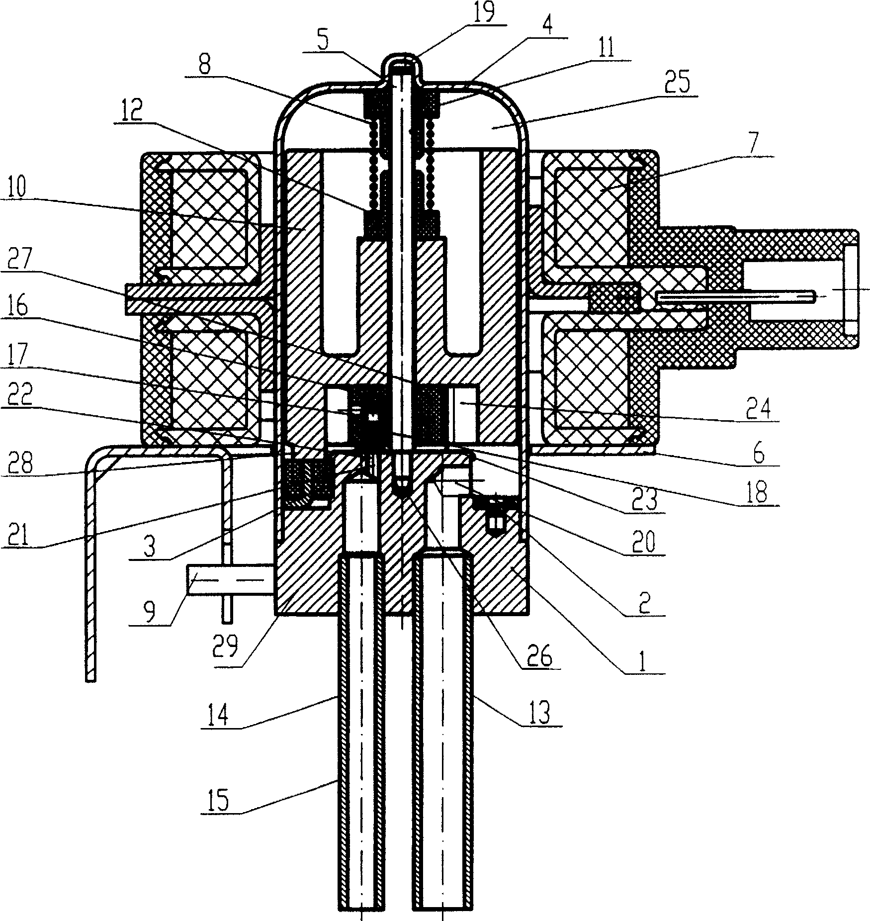
[0056] figure 2 The electric switching valve shown in ~ 4 has a valve body part formed by sealing the valve seat 1 and the shell 4 through welding and other methods, and the valve cavity 25 formed thereby.
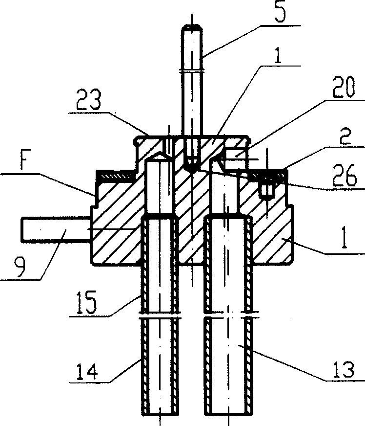
[0057] The electric switching valve has a valve seat part 29 with a normally open inlet pipe 13 and two outlet pipes 14 and 15 that are opened and closed as required, a rotating shaft 5 and a stopper 2 equipped with a rubber part 3: on the valve seat 1 There is an inlet 20 on the side of the upper step and is connected to the inlet pipe 13. There are outlets 21 and 22 on the upper end surface 23 of the valve seat. The outlet 21 is connected to the outlet pipe 14, and the outlet 22 is connected to the outlet pipe 15. The outlets 21 and 22 are distributed With the center hole 26 of the valve seat of the sealing surface 23 as the center, the radius is the same, and there is a certain distance on the circumference.
[0058] The small end of the rotating shaft 5 is closely ma...
Embodiment 2
[0075] refer to figure 2 , Figure 3, Figure 5 introduces the rotary solenoid valve of the second embodiment of the present invention.
[0076] Compared with the first example, the electric switching valve of this embodiment only changes the structure of the rotating bracket 16B, so the structure mentioned above will not be repeated.
[0077] From the comparison of Fig. 4 and Fig. 5, it can be seen that the difference of the rotating bracket 16B of this embodiment is that only an inner edge 16B1 supporting the valve core is provided on the inner edge of the fan-shaped groove, which has the advantage of reducing The contact area also reduces the friction resistance, which is beneficial to improve the valve opening ability of the product.
[0078] This embodiment can also realize the four working modes shown in FIG. 7 .
Embodiment 3
[0080] refer to figure 2 , Figure 3, Figure 6 introduces the rotary solenoid valve of the third embodiment of the present invention.
[0081] Compared with the first example, the rotary solenoid valve of the third embodiment only changes the structure of the rotating bracket 16, so the structure mentioned above will not be repeated.
[0082] From the comparison of Fig. 4 and Fig. 6, it can be seen that the difference of the rotating bracket 16C of the third embodiment is that only an outer edge 16C2 supporting the valve core is provided on the outer edge of the fan-shaped groove. It is to reduce the contact area, which also reduces the frictional resistance, which is beneficial to improve the valve opening ability of the product.
[0083] The third embodiment can also realize the four working modes shown in FIG. 7 .
PUM
 Abstract
Description
Claims
Application Information
 - R&D
- Intellectual Property
- Life Sciences
- Materials
- Tech Scout
- Unparalleled Data Quality
- Higher Quality Content
- 60% Fewer Hallucinations
Browse by: Latest US Patents, China's latest patents, Technical Efficacy Thesaurus, Application Domain, Technology Topic, Popular Technical Reports.
© 2025 PatSnap. All rights reserved.Legal|Privacy policy|Modern Slavery Act Transparency Statement|Sitemap|About US| Contact US: help@patsnap.com