
Coolant injection process and suitable clamping fixture for same

A cooling liquid and process technology, which is applied in the field of cooling liquid injection process and fixtures suitable for this cooling liquid injection process, can solve the problem of labor time and labor cost consumption, reduced reliability of projection tubes, and affecting the cooling effect of cooling liquid on the optical properties of projection tubes and other issues to achieve the effect of improving the process qualification rate

Inactive Publication Date: 2009-02-25
CHUNGHWA PICTURE TUBES LTD
View PDF4 Cites 0 Cited by
  • Summary
  • Abstract
  • Description
  • Claims
  • Application Information

AI Technical Summary

Problems solved by technology

From the above, it can be found that the known cooling liquid injection process needs to supplement the insufficient cooling liquid by manual filling, so it is easy to cause a waste of man-hours and labor costs
[0005] In addition, it is known that the process of manually installing the oil seal ring is carried out in an atmospheric environment, so it is easy to seal air into the interior of the projection tube during the installation process, and form air bubbles in the projection tube
These bubbles will affect the optical properties of the projection tube and the heat dissipation effect of the coolant, resulting in a decrease in the reliability of the projection tube

Method used


Image

  • Coolant injection process and suitable clamping fixture for same
  • Coolant injection process and suitable clamping fixture for same
  • Coolant injection process and suitable clamping fixture for same

Examples


Embodiment Construction

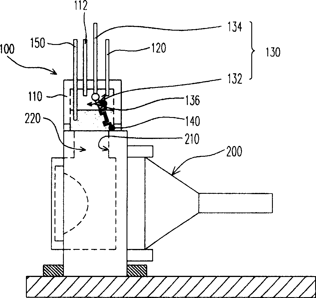
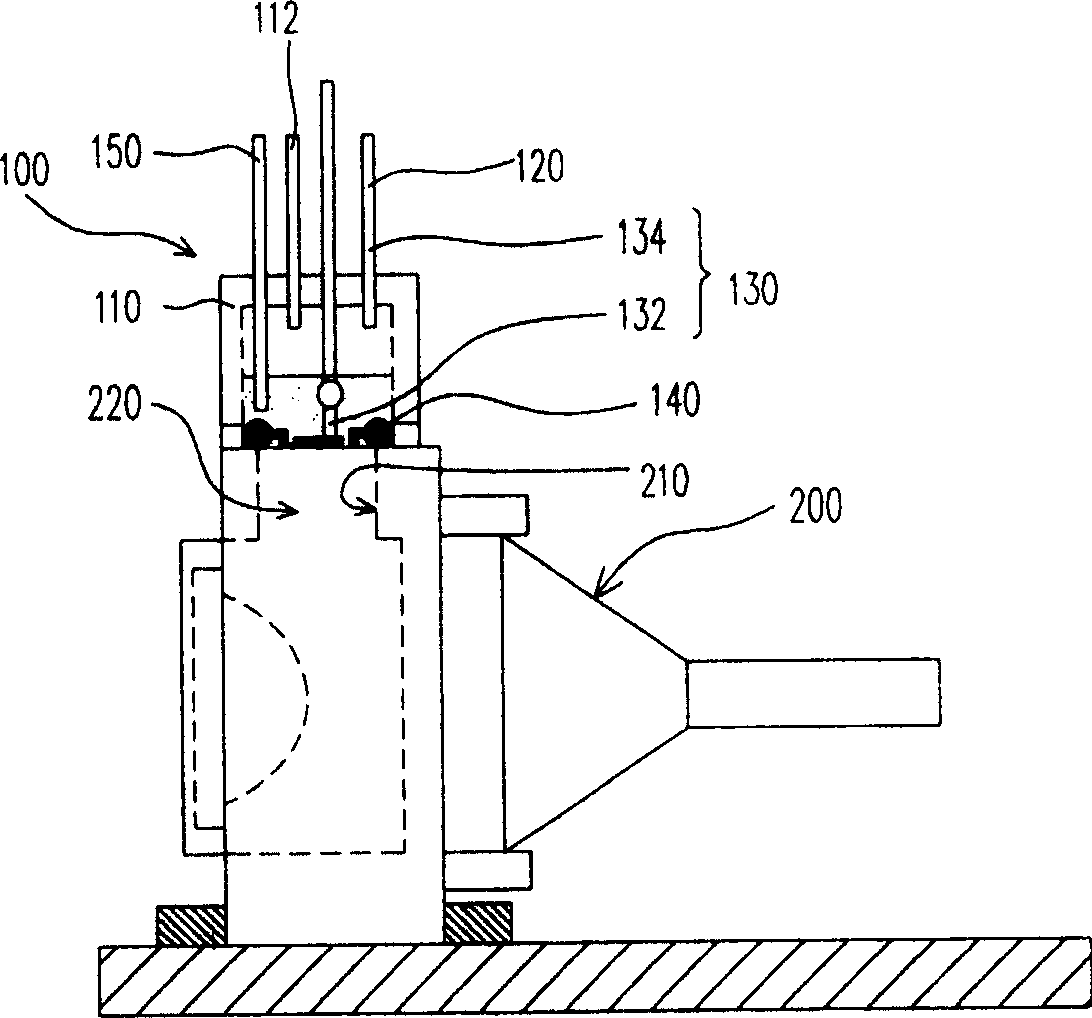
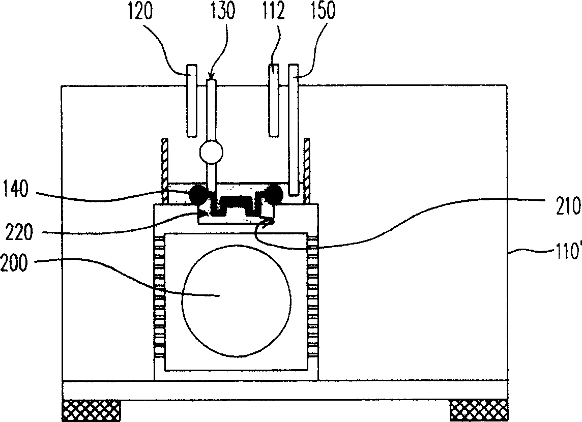
[0042] Figure 1A-1B It is a schematic diagram of a coolant injection process according to an embodiment of the present invention. Please refer to Figure 1A , the projection tube 200 has a cooling liquid injection port 210 and a chamber body 220 , and the cooling liquid injection port 210 and the chamber body 220 communicate with each other. In addition, the coolant injection fixture 100 includes a cover 110 , a liquid injection pipe 120 and a positioning device 130 . The cover 110 covers the coolant inlet 210 and is connected to a vacuum pump through a pipe 112 . In this way, a vacuum chamber can be formed in the cover body 110 through the suction of the vacuum pump, so that the chamber body 220 is in a negative pressure environment. In addition, the liquid injection pipe 120 is disposed in the cover body 110 for injecting cooling liquid into the chamber body 220 under a negative pressure environment.

[0043] Based on the above, the positioning device 130 is fixed inside...


PUM


Abstract

This invention relates to cooling liquid injection process, which comprises the following steps: a, setting one sealed element into cooling liquid injection entrance; then under one negative environment injecting the liquid into projection tube to facilitate cooling liquid higher than cooling liquid mouth; then injecting sealed parts into injection mouth sealing; then injecting cooling liquid into cooling liquid. This invention provides one cooling liquid injection clamper into projection tube.

Description

technical field [0001] The invention relates to a liquid filling process and a fixture suitable for the liquid filling process, and in particular to a cooling liquid injection process and a fixture suitable for the cooling liquid injection process. Background technique [0002] In a cathode ray tube (CRT) display, the projection tube is a very important component. In order to prevent the performance of the rear projection tube from being degraded or even damaged due to the heat generated in the working process, a coolant is usually poured into the rear projection tube to remove heat through heat conduction and heat convection of the coolant. [0003] A known coolant injection process is described below. First, use a vacuum pump to create a negative pressure environment. Afterwards, the projection tube with an opening is put into the negative pressure environment, and the cooling liquid is injected into the projection tube through the opening, wherein the filling amount of ...

Claims


Application Information

Patent Timeline
Patent Type & Authority Patents(China)
IPC IPC(8): H01J9/00H04N5/74
Inventor 林威志吴世民莫启能
Owner CHUNGHWA PICTURE TUBES LTD
Learn More