Supercharge Your Innovation With Domain-Expert AI Agents!

A light modulator

A light modulator, a technology for modulating light, applied in instruments, optics, nonlinear optics, etc., and can solve problems such as difficulty in moving particles

Inactive Publication Date: 2009-03-04
KONINK PHILIPS ELECTRONICS NV
View PDF5 Cites 0 Cited by
  • Summary
  • Abstract
  • Description
  • Claims
  • Application Information

AI Technical Summary

Problems solved by technology

However, moving these particles is difficult

Method used


Image

  • A light modulator
  • A light modulator
  • A light modulator

Examples


Embodiment Construction

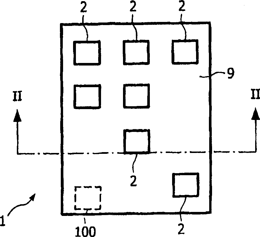
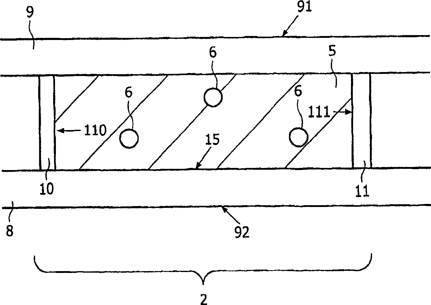
[0039] figure 1 with 2 An example of a light modulator as a display panel 1 having a first substrate 8 , a second transparent counter substrate 9 and a plurality of pixels 2 is shown. Preferably, the pixels 2 are arranged substantially along a straight line in the two-dimensional structure. Alternatively, other arrangements of pixels 2 are possible, such as a honeycomb arrangement. In an active matrix embodiment, the pixel 2 may also contain switching electronics such as thin film transistors (TFTs), diodes, MIM devices or other similar devices.

[0040]An electrophoretic medium 5 is located between the substrates 8, 9, which has first charged particles 6 in a transparent fluid. The surface 15 of the first substrate 8 facing the second substrate 9 may be transparent, reflective or of any colour. The substrate 8 may even be transparent if the panel 1 is used in light transmissive mode. Electrophoretic media 5 are known per se from eg US 2002 / 0180688. Pixel 2 has a light s...


PUM

PropertyMeasurementUnit
diameteraaaaaaaaaa

Abstract

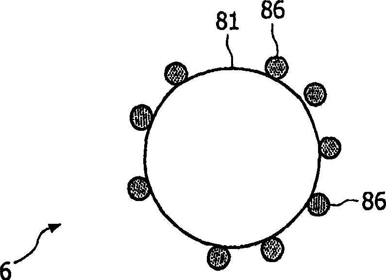
A light modulator for modulating light, having a light modulator unit and a particle controller (10, 11, 100), the unit having a medium containing particles (6) and a position dependent A light state, the controller being arranged to enable said particles (6) to move to one of the positions for modulating said light. Because the light modulator has a particle (6) that can be moved relatively easily, the particle (6) has a carrier (81) and a light particle (86), wherein the carrier has the ability to move the particle (6) during operation Contributing substantially non-contributing to said light state, while the light particles therein have optical properties that contribute to said light state, are related to said charge carriers (81), and have (81) The location of the location.

Description

technical field [0001] The invention relates to a light modulator for modulating light. The invention also relates to a device comprising such a light modulator. Background technique [0002] A light modulator for modulating light is disclosed in WO 03 / 071348. The disclosed light modulator is an electrophoretic display panel for producing color images. The panel has pixels with an electrophoretic medium that is substantially transparent in the spectral range and cyan particles for absorbing red light, violet particles for green light and yellow particles for blue light. In order for these particles to be transparent for non-absorbing wavelengths, the size of the light-absorbing layer / structure in the particle must be below the internal wavelength of light in the particle, ie the wavelength at which light is cut out by the particle's refractive index. For this purpose, small, nanometer-sized particles can be used. Alternatively, large, porous particles with a refractive i...

Claims


Application Information

Patent Timeline
Patent Type & Authority Patents(China)
IPC IPC(8): G02F1/167G02F1/1685
CPCG02F1/167G02F1/1685G02F1/0018G02F1/16757G02F2202/36G02F2202/04G02F2001/1678G02F2202/043
Inventor P·贝斯朱M·T·约韩逊L·J·M·施兰根G·H·里特詹斯M·R·博默P·C·多内弗尔德
Owner KONINK PHILIPS ELECTRONICS NV
Features
  • R&D
  • Intellectual Property
  • Life Sciences
  • Materials
  • Tech Scout
  • Unparalleled Data Quality
  • Higher Quality Content
  • 60% Fewer Hallucinations
Learn More