Brake actuating system using an electric motor

一种刹车片、致动装置的技术,应用在刹车致动装置领域,能够解决结构复杂、生产成本增加、难制造和装配等问题

Inactive Publication Date: 2009-03-18
WHEEL CORP
View PDF6 Cites 6 Cited by
  • Summary
  • Abstract
  • Description
  • Claims
  • Application Information

AI Technical Summary

Problems solved by technology

Therefore, its disadvantage is that the structure of the device is complicated, it is difficult to manufacture and assemble the device, and the production cost increases

Method used


Image

  • Brake actuating system using an electric motor
  • Brake actuating system using an electric motor
  • Brake actuating system using an electric motor

Examples


Embodiment Construction

[0040] Hereinafter, preferred embodiments of the present invention will be described in detail with reference to the accompanying drawings.

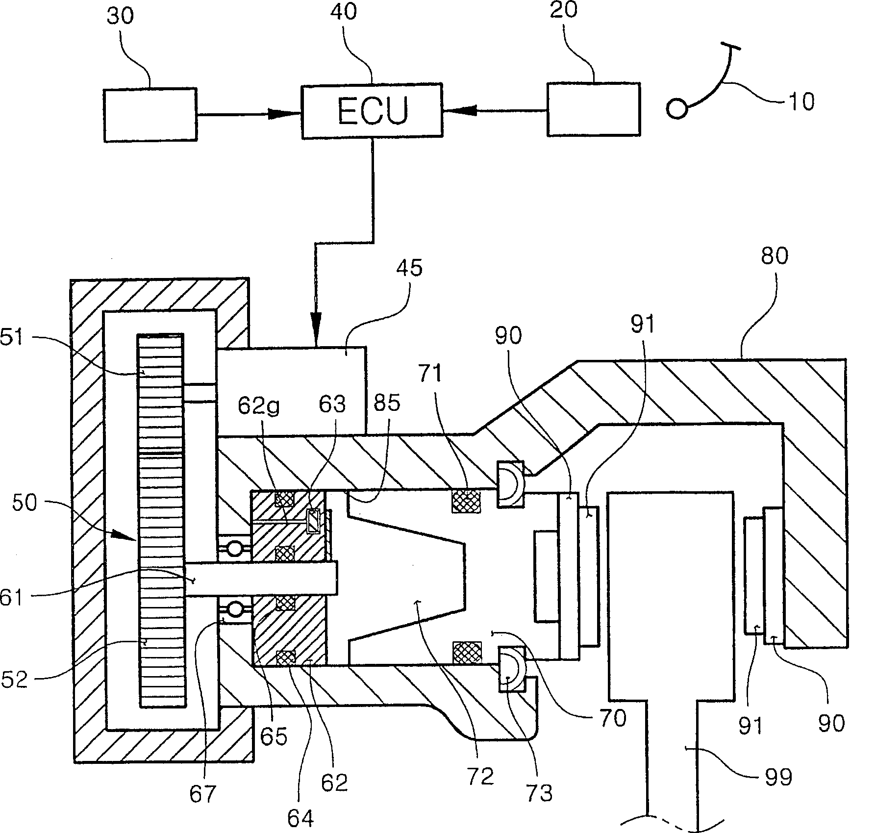
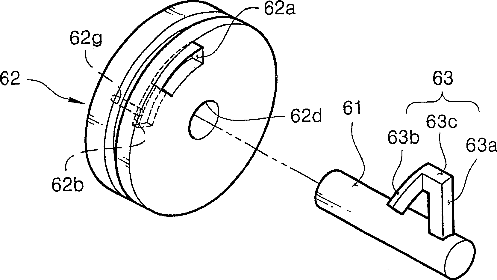
[0041] figure 1 is a schematic diagram of a brake actuating device according to an embodiment of the present invention, figure 2 yes figure 1 A perspective view of one embodiment of the housing and fluid booster components of the brake actuating device shown in FIG.

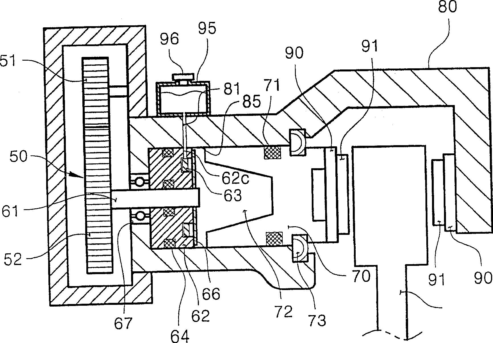
[0042] Such as figure 1 As shown in , the brake actuating device of this embodiment includes: a clamp body 80 with a cylinder 85; a motor 45 fixed to the clamp body 80; a pressure piston 70 installed in the cylinder 85; a housing 62, which Spaced from the pressure piston 70 with a predetermined distance in the back, and is fixedly installed on the cylinder 85 to maintain airtightness with the inner circumference of the cylinder 85; the rotating shaft 61 installed in the center of the housing 62 is transmitted by the motor 45 and the power transmission mechanism 50 f...


PUM


Abstract

A brake actuating apparatus includes a caliper body with a cylinder. An electric motor is fixed to the caliper body. A piston is installed in the cylinder. A plug and a rotational shaft are installed in the cylinder to be rotated by the motor. A head is attached to the rotational shaft and the plug defines a fluid-receiving space. The rotation of head varies the volume of a fluid contained in the fluid-receiving space, thereby moving the piston.

Description

technical field [0001] The present invention relates to a brake actuating device using a motor, and more particularly, to a brake actuating device capable of realizing a braking function without converting a rotational motion of a motor into a linear motion. That is, the present invention relates to a brake actuator having a fluid pressurizing member rotated by receiving a rotational force of a motor to pressurize fluid contained in a cylinder of a caliper and thereby push a piston of the caliper. Background technique [0002] A conventional type of hydraulic brake device generally includes a hydraulic circuit in which pedal pressure generated by a driver depressing a pedal is increased in a master cylinder and a force multiplier, and then transmitted to a brake device mounted to each wheel through a fluid pipe. The disadvantage of conventional hydraulic brakes is that braking cannot be achieved if the liquid pipe is damaged, and it takes a lot of time to transmit the pedal'...

Claims


Application Information

Patent Timeline
Patent Type & Authority Patents(China)
IPC IPC(8): B60T13/74F16D65/14
CPCF16D2127/04F16D2125/36F16D65/18B60T13/745F16D2123/00F16D2121/14F16D65/0075F16D2121/24F16D2125/10F16D2125/48B60T8/326F21S8/085F21V7/0033F21V7/22F21W2131/103
Inventor 赵韩龙
Owner WHEEL CORP
Why Eureka
Try Eureka